Glasfaserkabel vs Twisted-Pair-Kabel vs Koaxialkabel
Glasfaser-, Twisted-Pair- und Koaxialkabel sind drei Haupttypen von Netzwerkkabeln, die in Kommunikationssystemen verwendet werden. Was ist der Unterschied im Bereich der Leistung und Kapazität bei Glasfaserkabel gegenüber einem Twisted-Pair-Kabel oder einem Koaxialkabel?
Was ist ein Glasfaserkabel?
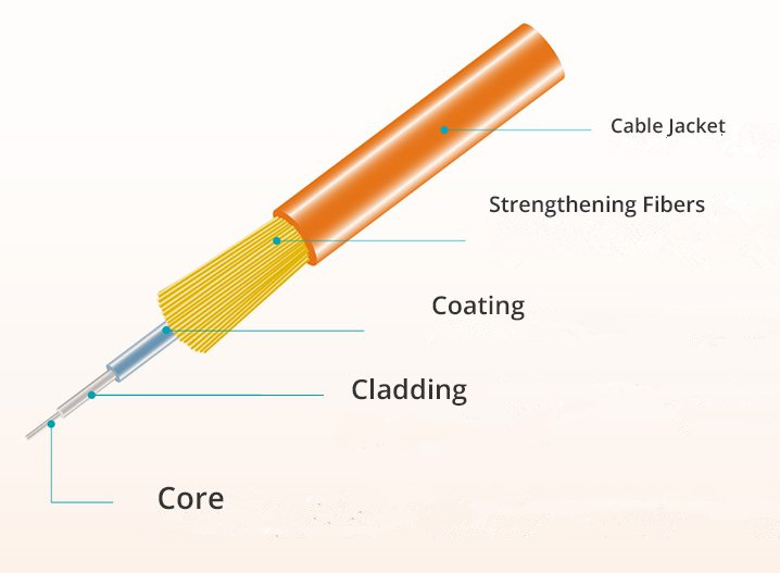
Ein Glasfaserkabel ist ein Ethernet-Kabel, das aus einer oder mehreren Glasfasern besteht, die zur Datenübertragung verwendet werden. Das Glasfaserkabel überträgt Daten, wenn Lichtimpulse durch winzige Glasröhren laufen. Glasfaserkabel können in Single-Mode-Fiber (SMF) und Multimode-Fiber (MMF) unterteilt werden. SMF hat einen kleinen Kern und ermöglicht nur die Ausbreitung einer einzigen Lichtart. Das MMF-Glasfaserkabel hingegen verfügt über einen größeren Kern und ist für die gleichzeitige Übertragung mehrerer Lichtstrahlen oder -modi ausgelegt. Das gewöhnliche SMF Kabel ist ein OS2-Kabel, während das MMF-Kabel ein OM1-, OM2-, OM3-, OM4- und OM5-Kabel ist. Die Übertragungsdistanz von Singlemode-Glasfaserkabeln beträgt mehrere Kilometern, während die Multimode-Glasfaser in einem 10G-Netzwerk nur bis zu 550 Meter beträgt. Um mehr über Glasfaserkabeltypen, Funktionsprinzip und Installationshinweise zu erfahren, lesen Sie bitte: Die Vorteile und Nachteile von Glasfaserkabeln.
Was ist ein Twisted-Pair-Kabel?
Twisted-Pair-Kabel werden häufig in der Telefonkommunikation und den meisten modernen Ethernet-Netzwerken verwendet. Es ist eine spezielle Art der Verdrahtung, bei der zwei Leiter einer einzelnen Schaltung miteinander verdrillt sind. Ein Kabelpaar bildet eine Schaltung, die Daten übertragen kann. Die Paare sind miteinander verdreht, um einen Schutz gegen„ Crosstalk“ zu bieten – von benachbarten Paaren erzeugte Geräusche.

Es gibt zwei Arten von Twisted-Pair-Ethernet-Kabeln: Unshielded-Twisted-Pair (UTP) und Shielded-Twisted-Pair (STP). Das häufig verwendete UTP-Kupferkabel ist Cat5, Cat5e, Cat6, Cat6a und Cat7. Das STP-Kupferkabel ist außen mit einem Drahtpaar umwickelt. Die vier Adernpaare werden dann in ein metallisches Geflecht oder eine Folie gewickelt – üblicherweise ein 150-Ohm-Kabel. STP-Kabel können Rauschen besser widerstehen als UTP-Kabel.
Was ist ein Koaxialkabel?
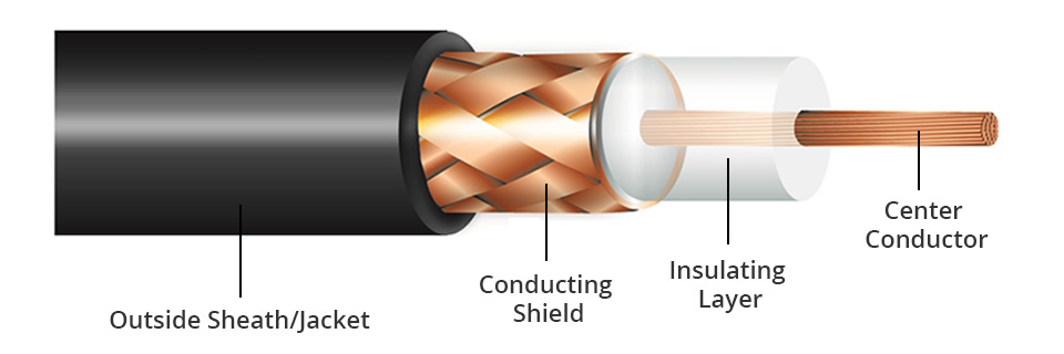
Koaxialkabel sind für die Übertragung hochfrequenter Signale ausgelegt. Sie bestehen aus einem runden Kupferleiter und drei Schichten Isolierung und Abschirmung, die „Crosstalk“ durch EMI-Quellen verhindern. Mit der Schirmkonstruktion kann das Koaxialkabel längere Kabellängen zwischen zwei Geräten unterstützen.
Es gibt verschiedene Arten von Koaxialkabeln, aber nur zwei – RG59 und RG6 – werden im Wohnbereich am meisten eingesetzt. Der Name "RG" stammt aus dem Zweiten Weltkrieg und bedeutet "Radio Guide", was heute keinerlei spezielle Bedeutung mehr hat.
Glasfaserkabel vs Twisted-Pair-Kabel vs Koaxialkabel: Was sind die Unterschiede?
Koaxialkabel und Twisted-Pair-Kabel sind Kupfer- oder Kupferdrähte, die von anderen Materialien umgeben sind. Beide können mit elektrischen Signalen Fernsehen, Telefon und Daten übertragen. Glasfaserkabel können die gleichen Arten von Signalen mit viel größerer Bandbreite, höherer Geschwindigkeit und höheren Frequenzen liefern. Es besteht aus sehr dünnen, biegsamen Rohren aus Glas oder Kunststoff.
Aus der Tabelle können wir ersehen, dass das Glasfaserkabel bei gleicher Kabellänge den niedrigsten Preis hat. Die Gesamtinstallation von Glasfaserkabeln kann jedoch aufgrund anderer verwendeter optischer Komponenten, insbesondere optischer Transceiver relativ hoch sein. Darüber hinaus kosten Twisted-Pair-Kabel mit RJ45-Stecker weniger als Koaxialkabel, die häufig mit einem BNC-Stecker ausgestattet sind.
Das Glasfaserkabel bietet zwar große Vorteile hinsichtlich der Flexibilität, Bandbreite und Zuverlässigkeit, ist jedoch nicht so weit verbreitet wie Koaxial- oder Twisted-Pair-Kabel. Zudem ist die Glasfaser empfindlicher und dünner als Twisted-Pair- und Koaxialkabel, weshalb sie mehr Sorgfalt bei Installation, Betrieb und Wartung benötigt. Im Vergleich zu Twisted-Pair-Kabeln kann ein Koaxialkabel eine größere Entfernung erreichen. Aufgrund des dielektrischen Isolators um dem Kupferkern des Koaxialkabels ist es jedoch schwierig, Koaxialkabel zu installieren und zu warten.
Glasfaserkabel werden nicht nur zur Unterstützung von Fernverbindungen zwischen Städten und Ländern installiert, sondern auch für direkten Zugang in Vororten mit FTTH, FTTP, FTTB, FTTC usw., die als "Letzte Meile"-Installationen bezeichnet werden. Sie werden häufig in Rechenzentren eingesetzt, in denen große Datenmengen übertragen werden müssen.
Twisted-Pair-Kabel werden hauptsächlich in Telefonnetzen und Datennetzwerken verwendet. Zu den Anwendungen von Koaxialkabeln gehören Zuleitungen, die Funksender und -empfänger mit ihren Antennen verbinden, Verbindungen zu Computernetzwerken (Internet), digitales Audio (S/PDIF) und zum Verteilen von Kabelfernsehsignalen. Sie können auch für HD-Medienschnittstellenverbindungen verwendet werden.
Fazit
Es gibt offensichtliche Unterschiede zwischen Glasfaserkabel, Twisted-Pair-Kabel und Koaxialkabel. Faseroptik scheint der Trend für die steigende Nachfrage des Marktes zu werden, da sich die Technologie schnell entwickelt. Ob Twisted-Pair-Kabel, Koaxialkabel oder Glasfaserkabel gewählt werden, hängt jedoch immer noch stark von den jeweiligen Anwendungen, der Budgetübertragungsentfernung und der Leistung ab.
Quelle: Glasfaserkabel vs Twisted-Pair-Kabel vs Koaxialkabel
T568A vs T568B: Was ist der Unterschied zwischen Straight-Through- und Crossover-Kabeln?
Beim Anschließen eines Netzwerkkabels müssen die farbigen Drähte immer in einer bestimmten, vordefinierten Reihenfolge angeordnet werden. Vergleicht man T568A und T568B, wird von zwei separaten Verdrahtungsnormen gesprochen. Was ist also der Unterschied zwischen T568A und T568B? In diesem Blog-Beitrag möchten wir den Unterschied zwischen Straight-Through- und Crossover-Kabeln in aller Kürze vorstellen.
Was genau sind die T568A und T568B Verdrahtungsstandards?
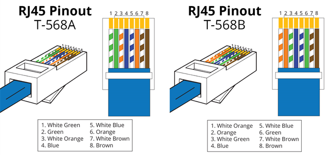
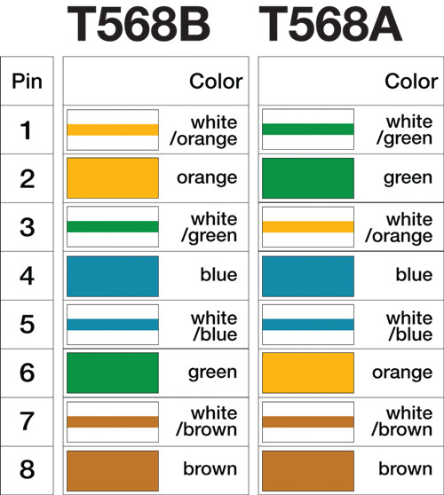
Netzwerkkabel enthalten vier Adernpaare, die jeweils aus einem durchgefärbten Draht und einem gestreiften derselben Farbe bestehen. Für ein 10/100BASE-T-Ethernet-Netzwerk werden nur zwei dieser Kabelpaare (orange und grün) verwendet. Die zwei anderen farbigen Kabelpaare (braun und blau) werden für andere Ethernet-Netzwerkanwendungen oder Telefonverbindungen verwendet. Je nach Verbindungsanforderung ist eine Straight-Through- oder Crossover-Verdrahtung erforderlich (direkte und gekreuzte Kabel). Um die Kabelanordnung zu normalisieren, werden zwei Standards zur Erstellung dieser Kabel verwendet: T568A und T568B. Diese beiden Verdrahtungsstandards bieten Schemata zum Anschluss von Netzwerkkabeln an acht RJ45-Steckern und -Buchsen.T568A vs. T568B.
Was sind Straight-Through- und Crossover-Kabel?
Ein Straight-Through-Kabel ist ein Twisted-Pair-Kabel, das in lokalen Netzwerken verwendet wird, um einen Computer mit einem Netzwerk-Hub wie einem Router zu verbinden. Diese Art von Kabel wird manchmal auch als Patchkabel bezeichnet und ist eine Alternative zu drahtlosen Verbindungen, bei denen ein oder mehrere Computer über ein drahtloses Signal auf einen Router zugreifen. Bei einem durchgehenden (Straight-Through“) Kabel dieser Art stimmen die verdrahteten Pins überein. Straight-Through-Kabel verwenden einen spezifischen Verdrahtungsstandard: Beide Enden verwenden den Verdrahtungsstandard T568A oder beide Enden verwenden den Verdrahtungsstandard T568B. Die folgende Abbildung zeigt ein durchgehendes Kabel, dessen beide Enden als T568B-Standard verdrahtet sind.
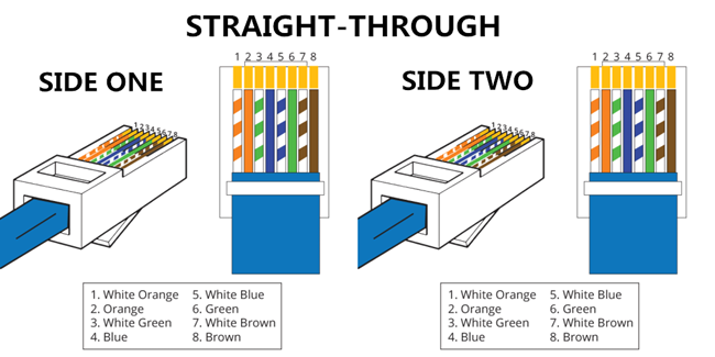
Abbildung 2: Pin-Belegung eines Straight-Through-Kabel.
Crossover-Kabel
Ein Ethernet-Crossover-Kabel ist ein Ethernet-Kabeltyp, mit dem Geräte direkt miteinander verbunden werden. Im Gegensatz zu einem Straight-Through-Kabel verwenden Crossover-Kabel zwei unterschiedliche Verdrahtungsstandards: Ein Ende verwendet den Verdrahtungsstandard T568A und das andere Ende den Verdrahtungsstandard T568B. Die interne Verdrahtung der Ethernet-Crossover-Kabel kehrt die Sende- und Empfangssignale um. Sie wird meistens verwendet, um zwei Geräte desselben Typs miteinander zu verbinden: zum Beispiel zwei Computer (über Netzwerkschnittstellen-Controller) oder zwei Switches.
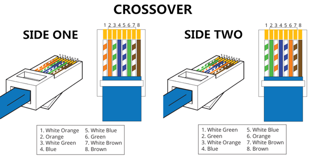
Abbildung 3: Pin-Belegung eines Crossover-Kabels.
Es gibt nur eine Möglichkeit, ein Cat5e-Crossover-Kabel herzustellen, und sie ist ziemlich einfach. Wer Teil zwei über Straight-Through-UTP-Kabel gelesen hat, weiß, dass ein UTP-Crossover-Kabel an einem Ende nach dem Standard 568A belegt ist, am anderen Ende nach 568B. Wie erwähnt besteht der Zweck eines Crossover-Kabels darin, die Sendeseite an einem Ende mit der Empfängerseite am anderen Ende (und umgekehrt) zu verbinden.
Wie Sie in Abbildung 3 sehen, werden für ein Crossover-Kabel lediglich vier Pins benötigt. Wenn Sie ein Crossover-Kabel kaufen, werden Sie möglicherweise feststellen, dass alle acht Pins belegt sind. Diese Kabel unterscheiden sich in nichts von der Variante mit vier Pins, denn die restlichen Kontakte werden nicht verwendet. Ob bei Ihrem Cat 5e UTP-Crossover-Kabel vier oder acht Pins verbunden sind, ist für die Performance belanglos.
Es ist wichtig, festzuhalten, dass Gigabit Ethernet ohne Crossover-Kabel auskommt. Hierbei kommen Straight-Through-Kabel zum Einsatz, und die Kabeladern werden automatisch von den Netzwerkkarten gekreuzt – Stichwort Auto-MDIX.
T568A vs T568B: Was sollte ich wählen?
Wie in der Abbildung unten dargestellt, besteht der Hauptunterschied zwischen diesen beiden Standards in der Position der orangefarbenen und grünen Drahtpaare. Natürlich ist dies nicht nur eine einzig optische Farbänderung. So sind Kompatibilitätsfaktoren weitere wichtige Unterschiede, die die Wahl eines RJ45-Verdrahtungsschemas beeinflussen können.
Straight-Through-ein Crossover-Kabel herstellen
Normalerweise werden Straight-Through-Kabel zum Verbinden von unterschiedlichen Geräten verwendet. Crossover-Kabel werden verwendet, um gleiche Geräten miteinander zu verbinden.
- Switch zu Router
- Switch zu PC oder server
- Hub zu PC oder server
- Switch zu Switch
- Switch zu Hub
- Hub zu Hub
- Router zu Router
- Router Ethernet port zu PC NIC
- PC zu PC
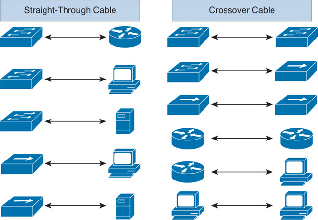
Abbildung 5: UTP-Crossover-Kabel und Straight-Through-Kabel.
Wo lassen sich Crossover-Kabel noch verwenden?
UTP-Crossover-Kabel werden nicht nur genutzt, um Computer zu verbinden, sondern auch eine Vielzahl von anderen Geräten. Typische Beispiele sind Switches und Hubs. Wer zwei Hubs miteinander verbinden muss, verwendet dazu in der Regel auf einer Seite den speziellen Uplink-Port. Dieser wird automatisch (früher auch durch einen kleinen Schalter) aktiviert und verhindert, dass die TX- und RX-Kabeladern intern gekreuzt werden. Das dazu genutzte Straight-Through-Kabel wird an einen normalen Port des zweiten Geräts angeschlossen.
Aber was, wenn keine Uplink-Ports vorhanden sind oder die bestehenden bereits verwendet werden? Dann ermöglicht Ihnen das Crossover-Kabel, beide Geräte miteinander zu verbinden, und löst so das Problem.
Wie in Abbildung 5 zu sehen, ist dank des Uplink-Ports kein Crossover-Kabel erforderlich.
Auch ohne diesen speziellen Port lassen sich die beiden Hubs miteinander verbinden. In dem Fall müssen wir auf ein UTP-Crossover-Kabel zurückgreifen:
So gut wie alle der heute auf dem Markt erhältlichen Switches unterstützen die Auto-MDIX-Funktion. Diese ermöglicht es, zwei Switches per Straight-Through-Netzwerkkabel miteinander zu verbinden.
Heutzutage ist der T568B-Standard bei Anwendern beliebter und hat T568A mittlerweise weitestgehend ersetzt. Insbesondere für neue Netzwerke, ohne vorbestehende Muster. Er stimmt nicht nur mit dem alten 258A-Farbcode von AT & T überein, sondern entspricht zudem den aktuellen und zukünftigen Anforderungen und ist abwärtskompatibel mit USOC. Es ist allerdings zu beachten, dass T568A und T568B nicht kombiniert oder ausgetauscht werden können.
Fazit
Straight-Through- und Crossover-Kabel sind in erster Linie unterschiedlich verdrahtet. Eine einfache Möglichkeit, um herauszufinden, mit welcher Art man es zu tun hat, ist die Prüfung der Reihenfolge der farbigen Drähte im RJ45-Stecker. Wenn die Reihenfolge der Drähte an beiden Enden gleich ist, handelt es sich um ein Straight-Through-Kabel. Wenn nicht, handelt es sich höchstwahrscheinlich um ein Crossover-Kabel oder das Kabel wurde falsch angeschlossen. Gegenwärtig ist das Straight-Through-Kabel viel beliebter als das Crossover-Kabel und wird häufiger verwendet. FS bietet ein komplettes Sortiment an Cat5e-, Cat6-, Cat6a- und Cat7-Ethernet-Kabeln mit vielen Längen- und Farboptionen. Suchen Sie nach Ethernet-Patchkabeln, finden Sie diese auf FS!
Quelle: T568A vs T568B: Was ist der Unterschied zwischen Straight-Through- und Crossover-Kabeln?
Was CWDM Mux/Demux ist und Wie installiert wird?
Die Technologie von Coarse-Wavelength-Division-Multiplexing (CWDM) wurde entwickelt, um die Kapazität eines Glasfasernetzwerkes zu erweitern, ohne zusätzliche Fasern zu benötigen. In einem CWDM-System ist CWDM MUX DEMUX (Multiplexer/Demultiplexer) die wichtigste Komponente und wird verwendet, um die aktuelle Faserkapazität zu erhöhen, indem mehrere Wellenlängen übertragen werden, typischerweise bis zu 18 getrennte Signale über eine Faser. Dieser Artikel stellt hauptsächlich CWDM-Technologie, CWDM-Multiplex-Demultiplexer und die Installation von CWDM MUX DEMUX vor.
Was CWDM Mux Demux Module ist?
Basierend auf verschiedenen Anwendungen kann ein CWDM-Modul(Multiplexer-Demultiplexer) in verschiedenen Kanälen entworfen werden. Ein typisches 4-Kanal-MUX-DEMUX-Modul wird verwendet, um vier verschiedene Wellenlängen auf eine Faser zu multiplexen (siehe Bild unten). Auf diese Weise können Sie vier verschiedene Daten gleichzeitig über dieselbe Glasfaser übertragen.
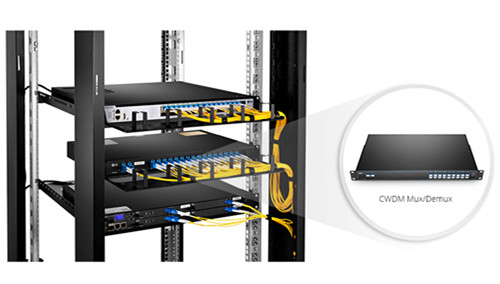
Based on different applications, a CWDM multiplexer demultiplexer module can be designed into different channels. A typical 4 channel MUX DEMUX module will be used to multiplex four different wavelengths onto one fiber (shown in the picture below). This allows you to simultaneously transmit four different data over the same fiber.
CWDM MUX/DEMUX Ports
Monitoranschluss—Fügt einen Monitor-Port auf CWDM oder DWDM MUX DEMUX hinzu, um die Netzwerküberwachung und -verwaltung zu verbessern.
Erweiterungsport—Verwenden Sie diesen Erweiterungsport, um den Kanal zu erweitern, indem Sie den Erweiterungsport mit dem Leitungsport eines anderen CWDM MUX DEMUX verbinden, der verschiedene Wellenlängen unterstützt. Sehen Sie sich das folgende Video an, um weitere Details von CWDM MUX DEMUX Ports zu erhalten.
1310nm Port and 1550nm Port—Der Port mit Standard-Kanal am WDM MUX/DEMUX kann nur an farbcodierte LWL-Transceiver wie CWDM SFP/SFP + angeschlossen werden. Mit diesen speziell entwickelten 1310nm- und 1550nm-Ports kann das Signal, das durch gewöhnliche faseroptische Transceiver läuft, mit anderen CWDM-Wellenlängen kombiniert werden.
Es können jedoch nicht alle Wellenlängen für CWDM MUX DEMUX hinzugefügt werden. Es gibt eine einfache Regel für das Hinzufügen der speziellen Ports und anderer Ports mit Standard-Kanal auf CWDM MUX DEMUX. Wenn Sie 1310nm- oder 1550nm-Ports auf Ihrem CWDM-MUX-DEMUX hinzufügen möchten, können die Wellenlängen, die 0-40nm höher oder niedriger als 1310nm oder 1550nm sind, nicht zum MUX hinzugefügt werden. Die obige Tabelle zeigt die spezifischen Details.
Anlagenkomponenten des CWDM MUX DEMUX Systems
Ein grundlegendes CWDM-MUX-DEMUX-System umfasst eine lokale Einheit, CWDM-MUX-DEMUX-Module und eine Ferneinheit. Eine lokale oder Remote-Einheit bezieht sich normalerweise auf einen Netzwerk-Switch. Um ein CWDM MUX DEMUX-Modul zu installieren, sollte im Allgemeinen zuerst ein Gehäuse installiert werden, um das Modul zu halten. Setzen Sie dann CWDM SFP/SFP + Transceiver in den Switch ein und verwenden Sie die Kabel mit Singlemode, um eine Verbindung zwischen LWL-Transceivern und CWDM MUX DEMUX-Modulen herzustellen. In der folgenden Tabelle sind die Installationskomponenten des CWDM MUX DEMUX-Systems aufgeführt.
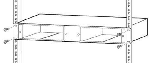
Das Rackmount-Chassis installieren
Das CWDM-Rackmount-Chassis kann in einem standardmäßigen 19-Zoll-Gehäuse oder Rack montiert werden. Stellen Sie beim Anschließen des Gehäuses an ein 19-Zoll-Standardrack sicher, dass Sie das Rackmount-Chassis im selben Rack oder einem benachbarten Rack Ihres Systems installieren, damit Sie alle Kabel zwischen CWDM-MUX-DEMUX-Modulen und den CWDM-SFP-Transceivern anschließen können.
Die CWDM MUX DEMUX-Module installieren
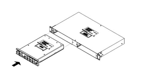
Um ein Modul einzufügen, sollten Sie das Modul zuerst auf das Chassisregal ausrichten (siehe Abbildung unten) und dann das Modul vorsichtig in das Fach drücken. Ziehen Sie schließlich die unverlierbaren Schrauben fest.
CWDM MUX DEMUX auf Switch verbinden
Nach dem Einlegen des CWDM SFP-Transceivers in den Netzwerk-Switch sollten wir das Kabel mit Singlemode verwenden, um den Transceiver mit dem CWDM MUX DEMUX zu verbinden.
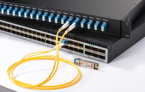
CWDM MUX DEMUX-Paare müssen LWL-Transceiver mit der gleichen Wellenlänge tragen, weil jeder Transceiver nur am entsprechenden Port arbeitet und die Daten immer zwischen Geräten mit den gleichen Wellenlängen fließen. CWDM SFP-Transceiver mit unterschiedlicher Wellenlänge können einen anderen Farbcode haben. Verwenden Sie die CWDM SFP-Transceiver mit Farbcodes, die in der folgenden Abbildung dargestellt sind, um den CWDM MUX DEMUX mit Ihrem System zu verbinden.
CWDM MUX DEMUX Paare verbinden
Sobald Sie einen CWDM-Multiplexer an einem Ende Ihrer Netzwerke verwenden, müssen Sie einen Demultiplexer am anderen Ende der Netzwerke verwenden. Daher besteht der letzte Schritt zur Vervollständigung des CWDM-MUX-DEMUX-Systems darin, die MUX-DEMUX-Paare (oder Multiplexer und Demultiplexer) zu verbinden. Für Duplex-MUX-DEMUX muss ein Paar Patchkabel mit Singlemode verwendet werden. Für Simplex MUX DEMUX ist nur ein Patchkabel mit Singlemode ausreichend. Danach ist Ihr System von CWDM MUX DEMUX erfolgreich installiert.
Lösung für CWDM MUX DEMUX - FS.COM
CWDM MUX DEMUX, nur CWDM-Multiplexer und CWDM-Demultiplexer sind eine flexible, kostengünstige Lösung, die die Erweiterung vorhandener Faserkapazität ermöglicht und Betreibern ermöglicht, die verfügbare Glasfaserbandbreite in lokalen Schleifen- und Unternehmensarchitekturen voll auszunutzen. Alle diese CWDM MUX/DEMUX Ports können in FS.COM angepasst werden, wo kostengünstige Komplettlösungen für CWDM, DWDM und DWDM über CWDM Netzwerk verfügbar sind. Weitere Informationen erhalten Sie unter sales@fs.com.
LWL-Singlemode vs Multimode: Was ist der Unterschied?
Die steigende Nachfrage nach Verbindungen mit höherer Bandbreite und schnellerer Geschwindigkeit hat das Wachstum des Marktes für faseroptische Kabelkonfektionen, insbesondere der Singlemode-Faser (SMF) und Multimode-Kabel (MMF), erheblich verbessert. Obwohl diese beiden Arten von Glasfaserkabeln in verschiedenen Anwendungen weit verbreitet sind, ist das Problem - Singlemode vs Multimode: was ist der Unterschied - immer noch verwirrend. Der folgende Artikel wird sich auf die grundlegende Konstruktion, den Faserabstand, die Kosten und die Faserfarbe konzentrieren, um einen detaillierten Vergleich zwischen Singlemode- und Multimode-Fasern zu ermöglichen.
Singlemode vs Multimode: Unterschied
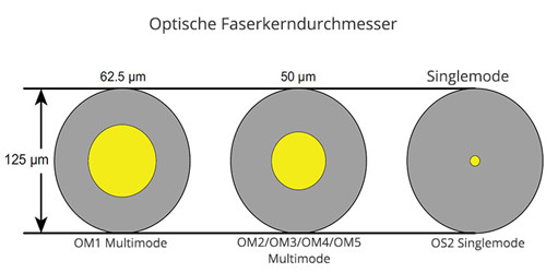
Singlemode bedeutet, dass die Faser ermöglicht, dass eine Art von Lichtmodus gleichzeitig propagiert wird. Multimode bedeutet, dass die Faser mehrere Modi übertragen kann. Der Unterschied zwischen Singlemode- und Multimode-Fasern liegt hauptsächlich in dem Faserkerndurchmesser, der Wellenlänge, der Lichtquelle und der Bandbreite.
Singlemode vs Multimode: Kerndurchmesser
Kerndurchmesser der Faser mit Singlemode ist viel kleiner als Faser mit Multimode. Der typische Kerndurchmesser beträgt 9 μm, auch wenn andere verfügbar sind. Der Faserkerndurchmesser mit Multimode beträgt typischerweise 50 μm und 62,5 μm, was ermöglicht, dass er eine höhere Lichtaufnahmefähigkeit hat und Verbindungen vereinfacht. Der Umhüllungsdurchmesser von Singlemode- und Multimode-Fasern beträgt 125 μm.
Singlemode vs Multimode: Wellenlänge & Lichtquelle
Aufgrund der großen Kerngröße bei Multimode-Lichtwellenleitern werden einige kostengünstige Lichtquellen wie LEDs (Licht emittierende Dioden) und VCSELs (oberflächenemittierende Laser mit vertikalem Resonator), die bei 850 nm und 1310 nm Wellenlänge arbeiten, in Multimodefaserkabeln verwendet. Während der Singlemode oft einen Laser oder Laserdioden verwendet, um in das Kabel injiziertes Licht zu erzeugen. Und die üblicherweise verwendete Singlemode-Faserwellenlänge ist 1310 nm und 1550 nm.
Singlemode vs Multimode: Bandbreite
Multimode-Faserbandbreite ist durch ihren Lichtmodus begrenzt, und die maximale Bandbreite beträgt derzeit 28000 MHz * km von OM5-Faser. Die Bandbreite der Singlemode-Glasfaser ist theoretisch unbegrenzt, da sie es ermöglicht, dass ein Lichtmodus gleichzeitig durchgeht.
Darüber hinaus gibt es auch einige Unterschiede zwischen Singlemode- und Multimode-Faserfarbe, lesen Sie den Artikel, um mehr zu bekommen: Wie identifiziert man den die Farbe der optischen Kabel?
Singlemode vs Multimode: Entfernung
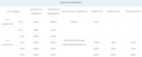
Es ist bekannt, dass eine Singlemode-Faser für Fernanwendungen geeignet ist, während eine Multimode-Glasfaser für Kurzstrecken ausgelegt ist. Wenn es dann um Singlemode vs Multimodefaserdistanz geht, was die quantifizierbaren Unterschiede sind?
Aus der Grafik können wir sehen, dass die Singlemode-Glasfaserdistanz viel länger ist als die von Multimode-Glasfaserkabeln bei einer Datenrate von 1G bis 10G, aber die OM3/OM4/OM5 Multimode-Glasfaser unterstützt eine höhere Datenrate. Da optische Multimodefasern eine große Kerngröße haben und mehr als eine Lichtmode unterstützen, ist ihre Faserdistanz durch Modelldispersion begrenzt, die ein häufiges Phänomen in Multimode-Stufenindexfaser ist. Während Singlemode-Faser nicht ist. Das ist der wesentliche Unterschied zwischen ihnen.
Singlemode vs Multimode: Verkabelungskosten
"Faserkosten für Singlemode vs Multimode" ist ein heißes Thema in einigen Foren. Viele Menschen haben ihre eigene Meinung geäußert. Ihre Ansichten konzentrieren sich hauptsächlich auf die Kosten für optische Transceiver, Systemkosten und Installationskosten.
Im Vergleich zu Singlemode-Transceivern ist der Preis für Multimode-Transceiver fast zwei- bis dreimal niedriger. Die folgende Cisco kompatible Singlemode-Transceiver und Multimode-Transceiver von FS.COM sind ein Beispiel.
Faser mit Singlemode sind im Allgemeinen für Anwendungen mit längerem Abstand ausgelegt, die LWL-Transceiver mit Lasern erfordern, die bei längeren Wellenlängen mit kleinerer Punktgröße und im Allgemeinen engerer spektraler Breite arbeiten. Diese Eigenschaften vom Transceiver in Verbindung mit der Notwendigkeit einer Ausrichtung mit höherer Genauigkeit und engeren Verbindertoleranzen für kleinere Kerndurchmesser führen zu signifikant höheren Transceiver-Kosten und insgesamt höheren Verbindungskosten für Singlemode-Faserverbindungen.
Herstellungsverfahren für VCSEL-basierte Transceiver, die für die Verwendung mit Multimodefasern optimiert sind, werden einfacher zu Array-Vorrichtungen hergestellt und sind kostengünstiger als äquivalente Singlemode-Transceiver. Trotz der Verwendung von mehreren Glasfaser-Lanes und Multi-Transceiver-Arrays gibt es signifikante Kosteneinsparungen gegenüber Singlemode-Technologie, die Single- oder Multi-Channel-Betrieb gegenüber Simplex-Duplex-Konnektivität verwenden.
Singlemode-Glasfaser kostet oft weniger als Multimode-Glasfaser. Wenn Sie ein 1G-Glasfasernetzwerk bauen, das 10G oder schneller sein soll, spart die Einsparung von Glasfaser für Singlemode ungefähr den halben Preis. Die Multimode-OM3- oder OM4-Faser erhöht die Kosten für SFP-Module um 35%. Die Monomode-Optik ist zwar teurer, aber die Arbeitskosten für den Austausch des Multimode sind deutlich höher, insbesondere wenn diese auf OM1-OM2-OM3-OM4 folgten.
Wenn Sie bereit sind, gebrauchte SFPs für ex-Fiberchannel zu betrachten, fällt der Preis für Singlemode-1G durch den Boden. Wenn Sie Budget für kurze 10G-Verbindungen haben, unterstützt die Wirtschaftlichkeitsprüfung bei der letzten Überprüfung immer noch Multimode. Behalten Sie diese Wirtschaftlichkeit jedoch im Auge, da die Geschichte darauf hindeutet, dass die Preisprämie für den Singlemode sinken wird.
Zusammenfassung
Das Singlemode-Glasfaserkabelsystem eignet sich für weitreichende Datenübertragungsanwendungen und wird häufig in Carrier-Netzwerken, MANs und PONs, eingesetzt. Multimode-Glasfaserkabel haben eine kürzere Reichweite und werden häufig in Unternehmen, Rechenzentren und LANs eingesetzt. Egal - welche Sie wählen, auf der Grundlage der gesamten Glasfaserkosten, ist es für jeden Netzwerk-Designer wichtig, die am besten zu geeigneten Produkten zu wählen.
Quelle: LWL-Singlemode vs Multimode: Was ist der Unterschied?
Grundlegendes zu Glasfaserstecker-Typen
Die Verwendung von LWL-Steckverbindern war das größte Problem bei optischen Systemen. Während optische Anschlüsse einmal unhandlich und schwierig zu verwenden waren, haben optische Verbinderhersteller in den letzten Jahren stark optische Stecker standardisiert und vereinfacht. Dies erhöht den Komfort bei der Verwendung von Lichtwellenleiteranschlüssen, der Reinigung von Lichtwellenleiteranschlüssen und der Terminierung in LWL-Systemen. Diese Anleitung bietet eine gründliche Analyse von Glasfasersteckern, einschließlich ihrer Struktur, Typen und Markttrends, um Ihnen bei der Auswahl der richtigen optischen Anschlüsse für Ihre optischen Verbindungen zu helfen.
Was ist Glasfaserstecker?
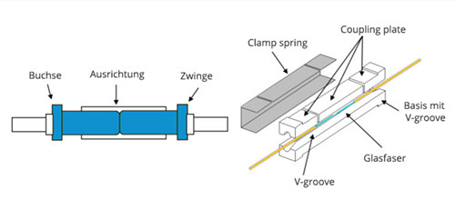
Glasfaserstecker, auch LWL-Kabelstecker genannt, ist eine Komponente, um das Ende des optischen Glasfaserkabels zu beenden und ermöglicht eine schnellere Verbindung und Trennung als LWL-Splicing. LWL-Kabelstecker gibt es in vielen Konfigurationen und Anwendungen und vereinfachen die Installation und Wartung von Glasfaserkabeln erheblich. Unterschiedliche Steckertypen haben unterschiedliche Eigenschaften, unterschiedliche Vor- und Nachteile und unterschiedliche Leistungsparameter. Aber alle Stecker haben die gleichen drei Grundkomponenten: Aderendhülse, Steckergehäuse, Kabel, Kupplungsvorrichtung.
Typen der LWL-Steckverbinder
Laut den verschiedenen Klassifizierungsmethoden können Glasfaserstecker in verschiedene Typen unterteilt werden. Zum Beispiel können sie entsprechend der Stiftendoberfläche des Steckers in PC, UPC und APC unterteilt werden. Nach Übertragungsmedium können Glasfaserstecker in Singlemode und Multimode aufgeteilt werden. Hier finden Sie eine Übersicht über die Steckverbinder, die in der Branche führend sind.
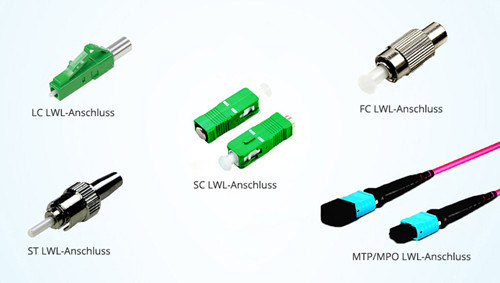
Der von Lucent Technologies entwickelte LC-Steckverbinder wurde zum allgegenwärtigen LWL-Steckverbinder für heutige optische Telekommunikationsanwendungen, insbesondere für Verbindungen mit SFP-und SFP+-LWL-Transceivern. Als ein beliebter SFF (Small Form Factor) Stecker hat der LWL-LC-Stecker eine Ferrule von 1,25 mm, die ihn perfekt für die Verkabelung mit hoher Dichte macht. Es gibt Singlemode LC Stecker und Multimode LC Stecker. Und basierend auf der Stecker-Konstruktion kann LC Stecker auch in LC-Duplex und Simplex-Stecker unterteilt werden.
Im Vergleich zu LC Stecker, verwenden LWL-SC-Stecker eine runde 2,5-mm-Ferrule, um eine Singlemode-Faser (SMF) zu halten. Und es hat einen "quadratischen" Stecker-Körper, der die Quelle des Namens "Quadrat Stecker" ist. Aufgrund seiner hervorragenden Leistung bleibt der faseroptische SC Stecker der zweithäufigste Stecker für polarisationserhaltende Anwendungen. LWL-SC-Stecker ist ideal für Datenkommunikations- und Telekommunikationsanwendungen geeignet, einschließlich Punkt-zu-Punkt-Netzwerken und passiven optischen Netzwerken.
MPO/MTP Stecker ist ein Mehrfaser-Stecker, der Fasern aus 12 bis 24 Fasern in einer einzigen rechteckigen Ferrule vereint. Es wird oft in parallelen 40G- und 100G-Parallelverbindungen verwendet. Verglichen mit anderen LWL-Steckern, die oben erwähnt wurden, sind MPO/MTP-LWL-Stecker komplizierter. Da gibt es Key-Up und Key-Down, männliche und weibliche MPO/MTP-Stecker. Für das verwirrende Problem-MPO-Stecker vs MTP-Stecker, erhalten Sie hier weitere Details: MPO/MTP Stecker: Empfehlung für Differenz und Reinigung
FC Stecker war der erste LWL-Stecker, der eine keramische Ferrule verwendete. Im Gegensatz zu SC und LC Stecker aus Kunststoff verwendet er eine runde Verschraubung aus vernickeltem oder rostfreiem Stahl. Die Stirnseite der FC-Stecker stützt sich auf einen Ausrichtungsschlüssel für das korrekte Einsetzen und wird dann in den Adapter festgezogen. Trotz der zusätzlichen Komplexität sowohl in der Fertigung als auch in der Installation ist FC Stecker immer noch der bevorzugte Steckverbinder für präzise Messgeräte wie OTDRs sowie die Wahl für Singlemode-Fasern.
ST Stecker wurde von AT & T entwickelt und lizensiert und ist immer noch einer der beliebtesten Stecker. Es hat eine Einfügedämpfung von etwa 0,25 dB und hält die Faser mit einer keramischen, federbelasteten 2,5-mm-Ferrule, die mit einer Bajonettfassung mit halber Verdrillung an Ort und Stelle bleibt. LWL-ST-Stecker werden normalerweise sowohl in Fern- als auch in Kurzstreckenanwendungen eingesetzt, z. B. in Campus- und Multimode-Glasfaseranwendungen, in Unternehmensnetzwerken und militärischen Anwendungen.
Simplex vs Duplex LWL-Stecker
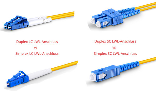
Die Verbindung von Simplex bedeutet, dass Signale in einer Richtung gesendet werden. Zum Beispiel wird ein Signal durch zwei Simplex-Stecker und ein Simplex-Faserkabel von Gerät A zu Gerät B übertragen. Es kann nicht über dieselbe Route von Gerät B zu Gerät A zurückkehren. Die Revisionsübertragung kann jedoch durch Duplex-Stecker und Duplex-Glasfaserkabel, die Duplexverbindung genannt werden, erreicht werden. Außerdem ist Simplex LWL-Stecker oft mit einem Strang Glas- oder Kunststofffaser verbunden, während Duplex LWL-Stecker mit zwei Fasersträngen verbunden sein müssen. Das folgende Bild zeigt den Vergleich von LC-Duplex-Stecker und SC-Duplex-Stecker.
Analyse für den Markt der LWL-Stecker
In den letzten Jahren wurde der globale Markt durch die zunehmende Verbreitung von Glasfasertechnologie angetrieben. Und LWL-Kabel sind weit verbreitet, um Kupferkabel zu ersetzen, die einen positiven Einfluss auf dem Matkt der LWL-Stecker haben. Hier ist ein Bericht über US-Markt von 2014 bis 2025 (USD Millionen)
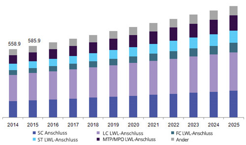
Aus dem Diagramm sehen wir, dass der Marktbedarf für MTP/MPO Stecker in den kommenden Jahren wachsen wird. LC LWL-Stecker besetzt immer noch den großen Markt. Diese zeigen, dass vielfache optische Stecker mit hoher Dichten, hoher Qualität immer noch große Verbesserungen haben. Und wir können davon ausgehen, dass die wachsende Nachfrage nach effizienter Verkabelung und Kabelmanagement, LWL-Stecker, die eine einfache Installation, geringen Faserverlust und hohe Leistung bieten, der neue Trend in der optischen Kommunikation sein wird.
10 Gigabit Ethernet SFP + Kabel Definition, Typen & Deployment Guide
Die Netzwerkverkabelung hat im Laufe der Jahre tief greifende Änderungen durchlaufen und macht einen großen Sprung nach vorn zu hoch Geschwindigkeits Faserkabeln. Aber in einigen Fällen, Kupfer Twinax Kabel, zB SFP+ Kabel oder SFP + DAC Twinax Kabel noch als eine optimierte Lösung für 10-GbE-Anwendungen über kurze Strecken. Dieser Beitrag stellt einige grundlegende Informationen über SFP + DAC-Kabel und Überlegungen für die Bereitstellung von 10 Gigabit-Ethernet-SFP +-Kabel.
SFP + Cable Basics: Definition & Typen
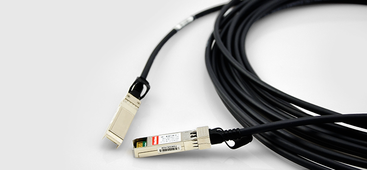
Das SFP + DAC Twinax-Kabel ist eine Kupferverbindung mit einer Twinax-Kabelkonfektion, die direkt in das SFP +-Gehäuse integriert wird. Durch die direkte Verbindung von zwei SFP + Slots eliminiert es effektiv den kostengünstigen optischen Transceiver, der in der Ausrüstung benötigt wird, und reduziert den Stromverbrauch, die Latenz und die Installationszeit erheblich. Daher hat sich das SFP + DAC-Kabel zu einer optimalen Wahl für moderne Kurzstrecken-Hochgeschwindigkeits-10-Gigabit-Ethernet-Anwendungen. Obwohl es eine Entfernungsbegrenzung von 10M hat, wird 10G SFP + DAC-Kabel häufig in Intra-Rack-und Inter-Rack-Verbindungen verwendet: einschließlich der Verbindung von Top-of-Rack-Switches mit Servern und Speichergeräten innerhalb eines Racks oder in benachbarten Racks.
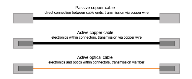
10-Gigabit-SFP + Direct-Attach-Kabel können in direkt anbringen Kupfer-Kabel (DAC) und direktes aktives optisches Kabel (AOC) klassifiziert werden. Das DAC-Kabel kann entweder passiv oder aktiv sein. Direktes aktives optisches Kabel AOC Bonds die Faserverbindung innerhalb des Transceivers endet, so dass eine komplette Faserkabel Montage ähnlich wie ein direktes Kupferkabel, aber mit einem 3-200 Meter erreichen Fähigkeit. Die obige Abbildung zeigt die führenden Typen von passiven und aktiven Direct-Attach-Kabeln für das Rechenzentrum Tor-Zusammenschaltung.
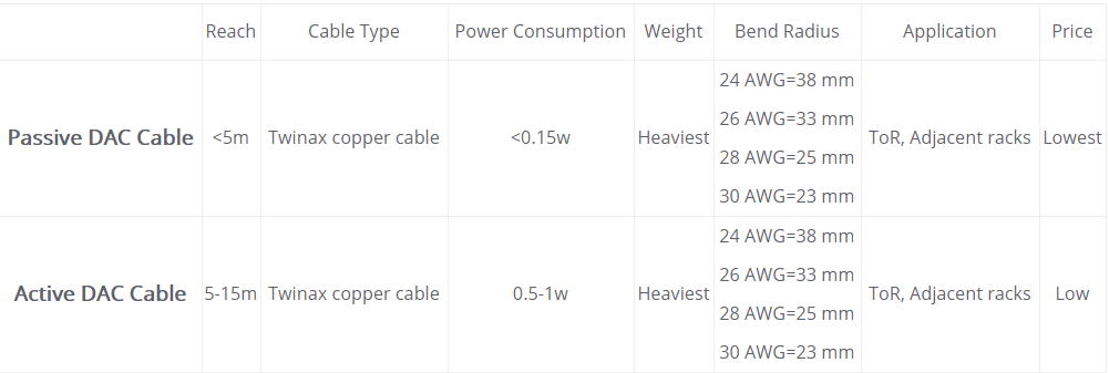
Passive DAC-Kabel enthält keine elektrischen Komponenten, so hat es minimalen Stromverbrauch von < 0.15 w, aber die Verknüpfung Abstand ist auf 5M begrenzt. Während aktive Kupferkabel enthält elektrische Komponenten in den Anschlüssen, die Signalpegel erhöhen können, so dass größere Entfernungen (5M oder mehr) über Kupfer-Medien und eine bessere Übertragungsqualität zu gewährleisten. Dies macht die aktiven Kupferkabel etwas teurer und verbraucht mehr Leistung als direkte Anbringen von passiven Kupferkabeln. Die Details sind in der folgenden Tabelle zu sehen.
SFP + Kabel Kauf Überlegungen
Als OEM oder Vendor Branded SFP + Twinax Kabel sind eher Kosten-unerschwinglich, sind die Nutzer eher geneigt zu wählen kompatiblen SFP + DAC-Kabel mit dem gleichen Industrie-Standard, aber nur einen Bruchteil der Kosten. FS.com SFP + zu SFP + Kabel ist getestet und mit Geräten von namhaften Herstellern kompatibel. Wir entwerfen auch speziell SFP + DAC Twinax Kabelkonfektionen mit unterschiedlichen Marken kompatiblen Gehäuse an zwei Seiten, und Sie können nach Ihren Bedürfnissen anpassen. Auf diese Weise ist das Anschließen von Switches von mehreren Anbietern kein Hindernis mehr.
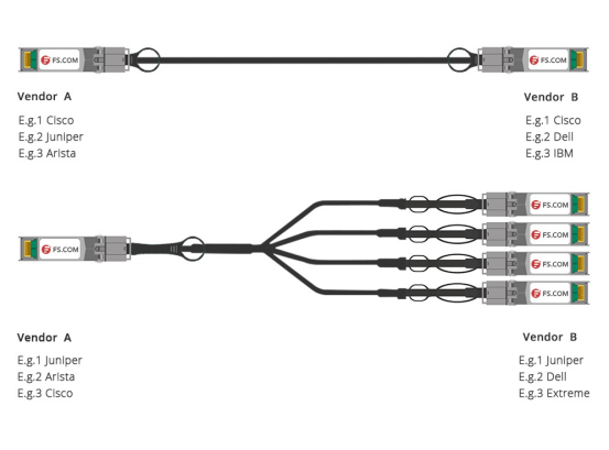
Produkt Details des SFP + DAC Twinax-Kabels lesen
Um die Kauf Besprechung mit ihren spezifischen Anforderungen zu treffen, sollten sich die Käufer der RoHS-Konformität, der Speichertemperatur und der MSA-Konformitäts Funktionen hinsichtlich der SFP + DAC Twinax-Kabel voll bewusst sein. Dies ist wichtig für die ordnungsgemäße Ausführung Ihres Netzwerksystems.
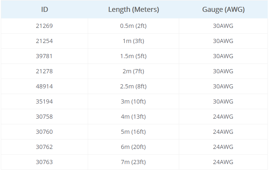
Ein weiterer wichtiger Faktor im Zusammenhang mit SFP + DAC Kupferkabel ist die AWG. Es gibt verschiedene Optionen von SFP + DAC Twinax Kabellänge und Draht Lehren, wie 24AWG, 28AWG und 30AWG. Beachten Sie bei der Wahl des AWG immer eine Regel: je länger der Abstand, desto niedriger ist die AWG-Bewertung. Gesehen in der unteren Bild, das Messgerät von SFP + Kabel 2M ist 30AWG, während SFP + Kabel 5M ist 24AWG.
SFP + Kabel Bereitstellungstipps
Hier bieten wir Antworten auf einige häufig gestellte Fragen über SFP + DAC Twinax Kabel, in der Hoffnung, es würde helfen, mit allen Verwirrungen in Bezug auf SFP + DAC Kupfer-Kabel befassen.
Passive SFP + DAC Twinax Kabel enthält keine elektrischen Komponenten, daher erfordert wenig oder gar keine Macht zu bedienen. SFP + Active Copper-Kabel, im Gegenteil, benötigt DC-Strom, um Signalverarbeitung Schaltung in seine eingebauten Anschlüsse integriert, so dass es teurer. Es wird empfohlen, passive SFP + DAC zu verwenden, wenn der Abstand nicht mehr als 7M beträgt. Wie für die Verbindung Abstand größer als 7 m (wie Tor zu EOR), aktive DACs erforderlich wäre.
Ja, genau wie optische Transceiver werden kompatible SFP + DAC Twinax-Kabel mit dem gleichen Industriestandard wie die Cisco-Kabel hergestellt. Ein qualifiziertes 10-GbE-SFP +-Kabel sollte getestet und von Cisco-Geräten vollständig erkannt werden, um eine einwandfreie Funktion zu gewährleisten. Holen Sie sich einen zuverlässigen Direct-Attach-Kabelhersteller, um SFP + DAC Twinax-Kabel zu kaufen, damit Ihr kompatibles SFP + DAC-Kabel genauso groß wie die Branded One-mit deutlich recuded Kosten-leisten kann.
Ja, SFP +-Kabel sind abwärtskompatibel zu SFP-Ports und funktionieren einwandfrei. SFP-Kabel sind jedoch nicht kompatibel zu SFP +-Ports. SFP-Kabel können an SFP +-Ports angeschlossen werden, Sie sind jedoch nicht für 10Gb/s-Datenraten ausgelegt.
Quellartikel:
https://www.fs.com/de/10-gigabit-ethernet-sfp-kabel-definition-typen-deployment-guide-aid-692.html
Warum passives SFP+ Kabel wählen?
Passive SFP+ Direct Attach Kupfer (DAC)-Kabel oder SFP+ zu SFP+ passive Kupferkabel sind 10-Gb-Kabelkonfektionen. Die Kabel entsprechen den SFF-8431-Spezifikationen und ermöglichen die Verbindung zwischen Geräten mit SFP+ -Ports. Und diese Kabel verwenden modernste Signalverarbeitungstechnologie, um den wachsenden Bedarf an kosteneffektiven Rechenzentrumsverbindungen zu decken. Warum würden Sie passives SFP+-Kabel wählen? Informationen zu passiven SFP+ -DAC-Kabeln werden in diesem Artikel angeboten.
Überblick über passives SFP+ Kabel
Die passive SFP+ DAC-Kabelkonfektion ist vollständig kompatibel mit dem SFF-8431 SFP+ MSA. Die Kabelkonstruktion besteht aus einem 100 zwei Paar abgeschirmten Twinax mit Ableitern für digitale Erde. Passives SFP+ Kabel ermöglicht eine serielle Datenübertragung von bis zu 12 Gbit/s in jeder Richtung. Das passive Design hat keine Signalverstärkung in der Kabelanordnung. Die elektronische Dispersionskompensation (Electronic Dispersion Compensation, EDC) wird typischerweise bei Host-Board-Designs verwendet, wenn passive Kupferkabelanordnungen verwendet werden. EDC ermöglicht eine erweiterte Länge von passiven Kabelkonfektionen. Das mechanische Design der Geflechtcrimp- und EMI-Ummantelung stellt sicher, dass EMI-Strahlung ausreichend unterdrückt wird. Zusätzlich fungiert das Kupferkabel als natürlicher Kühlkörper. Der geringe Stromverbrauch hilft dabei, die passive Kupferkabel-Baugruppe zu einer wirtschaftlichen Lösung für Rack- oder Rack-to-Rack-Anwendungen zu machen. Das folgende Bild zeigt ein HP J9281B kompatibles SFP+ zu SFP+ passives Kupferkabel.

Warum passives SFP+ DAC Kabel wählen?
Es gibt viele Lösungen für 10G-Ethernet-Anwendungen. Warum würden Sie SFP+ zu SFP+ passive Kupferkabel wählen? Als die Entwicklung der Fasertechnologie hat SFP+ zu SFP+ passives Kupferkabel immer noch seine Vorteile auf dem Markt. Jetzt können passive SFP+ DAC-Kabel höhere Datenraten unterstützen als herkömmliche Kupferschnittstellen. Mit der Entwicklung der Kupferkabeltechnologie ist passives SFP+ DAC-Kabel austauschbar und hot-swap-fähig mit Glasfasermodulen. Und vor allem sind SFP+ bis SFP+ passive Kupferkabel für sehr kurze Distanzen geeignet, einschließlich 1m, 3m, 5m, 7m, 10m usw. Sie bieten eine sehr kostengünstige Möglichkeit, innerhalb von Racks und über benachbarte Racks hinweg zu verbinden. Mit den SFP+ -Kupfermodulen können Hardwarehersteller eine hohe Portdichte, Konfigurierbarkeit und Auslastung bei sehr geringem Gewicht und reduziertem Strombudget erreichen.
Anwendungen von Passive SFP+ Kabel
Die passive SFP+ zu SFP+ Kupferkabel-Baugruppe erfüllt die Anforderungen von 10 Gigabit Ethernet, Fibre Channel und anderen Industriestandards für Leistung und Zuverlässigkeit. Sie unterstützen mehrere Protokolle wie Gigabit & 10G Ethernet, 1, 2, 4, 8 und 10G FC, Fibre Channel über Ethernet (FCoE) serielle Datenübertragung und Infiniband SDR, DDR und QDR. SFP+ zu SFP+ passive Kupferkabel sind Hochleistungs-I/O-Lösungen für 10G-Ethernet- und 10G-Fibre-Channel-Anwendungen.
Fazit
Passives SFP+ -Direct-Attach-Kupferkabel ist eine kostengünstige Lösung mit geringem Stromverbrauch und geringer Latenz, die sich ideal für hochdichte 10Gb / s-Verbindungen zwischen Servern und Switches im Rack eignet. Fiberstore fertigt und liefert eine komplette Palette passiver SFP+ Kupfer-Direktkabel für Ihre Anwendungen. Wir bieten kompatibles passives SFP+-Kabel als Alternative zu Markenherstellern wie Cisco, HP, Juniper. Zum Beispiel, Cisco SFP-H10GB-CU1-5M kompatibles SFP+ zu SFP+ passives Kupferkabel, HP J9285B und HP JG081C kompatibles SFP+ zu SFP+ passives Kupferkabel, sind alle diese passiven SFP+ Direktanschluss Kupferkabel mit hoher Qualität und voll kompatibel mit ihren Marken Firmen.
Funktioniert Cat6 auf Cat5e Patchpanel oder Cat5e auf Cat6 Patchpanel?
Auf dem Markt gibt es sowohl Cat5e Patchpanel als auch Cat6 Patchpanel. Wir wissen, dass Cat5e-Patch-Panels für die Verwendung mit Cat5e-Kabeln vorgesehen sind und Cat6-Patchpanels für die Verwendung mit Cat6-Kabeln, aber was ist der Unterschied zwischen Cat5e- und Cat6-Patch-Panels? Kann ich ein Cat6-Kabel an Cat5e-Schalttafeln verwenden oder kann ich Cat5e-Kabel an Cat6-Schalttafeln verwenden? Antworten werden in diesem Blog zur Verfügung gestellt.

Kann ich Cat6 auf Cat5e Patchpanel verwenden?
Es gibt nicht viel praktischen Unterschied in den Schalttafeln selbst. Es gibt einen Unterschied in der Drahtstärke zwischen Cat5e und Cat6. Der Cat6-Draht ist dicker. Cat6 hat normalerweise 23 AWG Kupferleiter, verglichen mit nur 24 AWG in Cat5e Kabel. Ein weiterer Faktor, der Cat6 zu einem größeren Draht als Cat5e macht, ist die Tatsache, dass zwischen jedem der vier Paare in einem Cat6-Kabel ein Spline vorhanden ist, der jedes Paar voneinander trennt. Das Trennen der Paare hilft, das Übersprechen zwischen den Paaren zu reduzieren und gibt Ihnen ein besseres Signal. Dieser Spline erhöht jedoch auch den Durchmesser des Kabels. Unabhängig vom Größenunterschied zwischen Cat5e und Cat6 war das Cat6-Kabel abwärtskompatibel zu Cat5e. Ja, Cat6 ist oft ein größeres Kabel, aber das ändert nichts an der Verwendung mit Cat5e Patchpanels. Fühlen Sie sich frei, Cat5e Patch-Panels zu verwenden, wenn Sie sie bereits haben. Sie können sie später jederzeit aktualisieren.
Kann ich Cat5e auf Cat6 Patchpanel verwenden?
Zusätzlich zur Verwendung von Cat6 auf dem Cat5e-Patchpanel können wir auch in einigen Situationen, in denen wir Cat5e auf einem Cat6-Patchpanel verwenden möchten, vorgehen. Laut dem obigen Abschnitt wissen wir, dass Cat6-Kabel dicker als Cat5e sind. Wenn ich Cat5e auf einem Cat6-Patchpanel verwende, ist es dann zu locker? Obwohl die einzelnen Twisted-Pair-Isolierungen von Cat6 normalerweise dicker sind als Cat5e, ist dies normalerweise nie ein Problem mit der Terminierung, sondern nur mit der Anzahl der Kabel, die Sie durch ein Stück Conduit stopfen können. Also, wird ein Cat5e-Kabel "looser" terminiert an einer Cat6-Buchse, ein wenig ja, aber elektrisch wird es immer noch Kontakt und funktioniert gut. Sie sollten jedoch beachten, dass Ihr Kabelkanal standardmäßig auf die niedrigste Catx-Komponente eingestellt wird. Auch wenn auf dem Patch-Panel Cat6 steht, sollten Sie bei Cat5e-Kabeln nur Cat5e-Performance an diesen Buchsen erwarten.
Fazit
Wenn Cat5e-Draht auf einem Cat6 niedergeschlagen wird, ist der Cat5e-Draht so klein, dass es möglich ist, etwas zu bekommen, was wie ein guter Schlag aussieht, aber die Isolation auf dem Draht wird nicht durchdrungen oder nur teilweise von der Vampirklaue des Stempels durchdrungen Block. Wenn Cat6-Kabel auf ein Cat5e-Panel gestanzt werden, kann das größere Kabel dazu führen, dass die Vampirbacken auf dem Stanzblock gebogen oder sogar gebrochen werden. In beiden Fällen können Sie in der Regel dafür sorgen, dass jede Verbindung ordnungsgemäß funktioniert und getestet wird. Wenn Sie nur ein Panel zu Hause machen, sind Sie wahrscheinlich in Ordnung. Obwohl es beides gut funktioniert, empfehlen wir nicht, dies zu tun. Verwenden Sie das Cat5e auf Cat5e Patchpanel und Cat6 auf Cat6 Patchpanel wird die beste Leistung erhalten. FS.COM bietet sowohl Cat5e-Patch-Panels mit hoher Dichte für Fast-Ethernet-Anwendungen als auch Cat6-Patchpanels für 1-Gigabit-Ethernet-Anwendungen. Einfach zu verwalten und spart Platz im Rechenzentrum.
Was ist der Unterschied: OM3 vs OM4
OM3 und OM4 sind zwei gebräuchliche LWL Multimode, die in lokalen Netzwerken verwendet werden, typischerweise in der Backbone-Verkabelung zwischen Telekommunikationsräumen und im Datenzentrum zwischen Hauptnetzwerk- und SAN-Switches (Storage Area Network). Beide dieser Fasertypen werden als laseroptimierte 50/125-LWL-Multimode, was bedeutet, dass beide einen Kern mit einem Kerndurchmesser von 50μm und einen Mantel mit 125μm Durchmesser haben, eine spezielle Beschichtung, die verhindert, dass Licht aus dem Kern austritt. Beide Fasertypen verwenden die gleichen Anschlüsse, den gleichen Abschluss und die gleichen Transceiver-oberflächenemittierende Laser mit vertikalem Resonator (VCSELs), die Infrarotlicht mit 850 Nanometern (nm) emittieren. LWL OM3 ist vollständig kompatibel mit OM4. Mit so vielen Ähnlichkeiten und oft mit der gleichen Farbe Aqua Kabelmantel und Stecker hergestellt, kann es schwierig sein, diese beiden Arten von Fasern auseinander zu unterscheiden. Also, was ist der Unterschied zwischen beiden ? Beziehen sich diese beiden Arten von Fasern auf dasselbe?

Was ist der Unterschied: OM3 vs OM4
Tatsächlich besteht der Unterschied zwischen om3 und om4 nur in der Konstruktion des Glasfaserkabels. Der Unterschied in der Konstruktion bedeutet, dass das OM4-Kabel eine bessere Dämpfung aufweist und mit einer höheren Bandbreite als LWL OM3 arbeiten kann. Was ist der Grund dafür? Damit eine Glasfaserverbindung funktioniert, hat das Licht vom VCSEL-Transceiver viel Energie, um den Empfänger am anderen Ende zu erreichen. Es gibt zwei Leistungswerte, die dies verhindern können-optische Dämpfung und modale Dispersion.
Dämpfung ist die Verringerung der Leistung des Lichtsignals, wenn es übertragen wird (dB). Die Dämpfung wird durch Lichtverluste durch die passiven Komponenten wie Kabel, Kabelspleiße und Anschlüsse verursacht. Wie oben erwähnt, sind die Anschlüsse die gleichen, so dass der Unterschied in der OM3- und OM4-Leistung im Verlust (dB) im Kabel liegt. OM4 LWL Multimode Kabel verursachen aufgrund ihrer Konstruktion geringere Verluste. Die maximale Dämpfung, die von den Standards zugelassen wird, ist unten gezeigt. Sie können sehen, dass die Verwendung von OM4 Ihnen geringere Verluste pro Meter Kabel bringt. Die niedrigeren Verluste bedeuten, dass Sie längere Verbindungen haben können oder mehr verbundene Verbinder in der Verbindung haben.
Maximale Dämpfung bei 850 nm erlaubt: OM3<3.5 dB/km; OM4<3.0 dB/km
Licht wird in verschiedenen Moden entlang der Faser übertragen. Aufgrund der Unvollkommenheiten in der Faser kommen diese Moden als etwas unterschiedliche Zeiten an. Wenn dieser Unterschied zunimmt, gelangen Sie schließlich zu einem Punkt, an dem die übertragenen Informationen nicht decodiert werden können. Dieser Unterschied zwischen dem höchsten und dem niedrigsten Modus wird als modale Dispersion bezeichnet. Die modale Dispersion bestimmt die modale Bandbreite, mit der die Faser arbeiten kann, und dies ist die Differenz zwischen OM3 und OM4. Je niedriger die modale Dispersion ist, desto höher ist die modale Bandbreite und desto größer ist die Menge an Information, die übertragen werden kann. Die modale Bandbreite von OM3 und OM4 ist unten gezeigt. Die höhere Bandbreite, die in OM4 zur Verfügung steht, bedeutet eine kleinere Modendispersion und erlaubt somit, dass die Kabelverbindungen länger sind oder höhere Verluste durch mehr verbundene Verbinder erlauben. Dies bietet mehr Optionen beim Betrachten des Netzwerkdesigns.
Minimale Glasfaserbandbreite bei 850 nm: OM3 2000 MHz·km; OM4 4700 MHz·km
Wählen Sie OM3 oder OM4?
Da die Dämpfung von OM4 niedriger als die LWL OM3 ist und die modale Bandbreite von OM4 höher als OM3 ist, ist die Übertragungsdistanz von OM4 länger als OM3. Details sind in der folgenden Tabelle aufgeführt. Wählen Sie entsprechend Ihrer Netzwerkskala einen geeigneteren Kabeltyp.

Da OM4 besser als OM3-Kabel ist, ist das OM4-Kabel in der Regel doppelt so teuer wie das OM3-Kabel. Dies kann ein großer begrenzter Faktor für die Anwendung von OM4-Kabeln sein. Wenn Sie sich jedoch entscheiden, in FS.COM einzukaufen, erhalten Sie möglicherweise viel billigere OM4-Fasern, fast die gleichen wie die LWL OM3. Jedes OM3-oder OM4-Kabel kann Ihren individuellen Verkabelungsanforderungen gerecht werden. Wählen Sie einfach den am besten geeigneten für Ihr Netzwerk, um weniger zu kosten und mehr zu erreichen.
Differences Between FBT Splitter and PLC Splitter
In FTTx and PON architectures, optical splitter plays an increasingly significant role to create a variety of point-to-multipoint fiber optic networks. But do you know what is a fiber optic splitter? In fact, a fiber optic splitter is a passive optical device that can split or separate an incident light beam into two or more light beams. Basically, there are two types of fiber splitter classified by their working principle: fused biconical taper splitter (FBT splitter) and planar lightwave circuit splitter (PLC splitter). You may have one question: what’s the difference between them and shall we use FBT or PLC splitter?

What Is FBT Splitter?
FBT splitter is based on a traditional technology to weld several fiber together from side of the fiber. Fibers are aligned by heating for a specific location and length. Because the fused fibers are very fragile, they are protected by a glass tube made of epoxy and silica powder. And then a stainless steel tube covers the inner glass tube and is sealed by silicon. As the technology continues developing, the quality of FBT splitter is very good and it can be applied in a cost-effective way.
| Advantages | Disadvantages |
|---|---|
|
|
What Is PLC Splitter?
PLC splitter is based on planar lightwave circuit technology. It composes of three layers: a substrate, a waveguide, and a lid. The waveguide plays a key role in the splittering process which allows for passing specific percentages of light. So the signal can be split equally. In addition, PLC splitters are available in a variety of split ratios, including 1:4, 1:8, 1:16, 1:32, 1:64, etc. They also have several types, such as bare PLC splitter, blockless PLC splitter, fanout PLC splitter, mini plug-in type PLC splitter, etc. Therefore, if high split counts are needed, small package size and low insertion loss are also required, you are suggested to choose PLC splitter rather than FBT splitter. For more information about PLC splitter, please refer to How Much Do You Know About PLC Splitter?
| Advantages | Disadvantages |
|---|---|
|
|
FBT vs. PLC Splitter
FBT splitter can only support three wavelengths: 850nm, 1310nm and 1550nm, which makes its inability to works on other wavelengths. While PLC splitter can support wavelength from 1260 to 1650nm. The adjustable rang of wavelength makes PLC splitter suitable for more applications.

Splitting ratio is decided by the inputs and outputs of an optical cable splitter. The maximum split ratio of FBT splitter is up to 1:32, which means one or two inputs can be splitted into an output maximum of 32 fibers at a time. However, the split ratio of PLC splitter is up to 1:64 - one or two inputs with an output maximum of 64 fibers. Besides, FBT splitter is customisable, and the special types are 1:3, 1:7, 1:11, etc. But PLC splitter is non-customisable, and it has only standard version like 1:2, 1:4, 1:8, 1:16, 1:32 and so on.

The signal processed by FBT splitters cannot be splitted evenly due to lack of management of the signals, so its transmission distance can be affected. However, PLC splitter can support equal splitter ratios for all branches, so it is more stable.

FBT splitter is typically used for networks requiring the splitter configuration of less than 4 splits. The larger the split, the larger failure rate. When its splitting ratio is larger than 1:8, more errors will occur and cause higher failure rate. Thus, FBT splitter is more restricted to the number of splits in one coupling. But the failure rate of PLC splitter is much smaller.

In certain areas, temperature can be a crucial factor that affects the insertion loss of optical components. FBT splitter can work stable under the temperature of -5 to 75℃. PLC splitter can work at a wider temperature range of -40 to 85 ℃, providing relatively good performance in the areas of extreme climate.
Owing to the complicated manufacturing technology of PLC splitter, its cost is generally higher than the FBT splitter. If your application is simple and short of funds, FBT splitter is definitely a cost-effective solution.
Conclusion
Although the outer appearance and size of FBT and PLC fiber splitter seem rather similar, their internal technologies and specifications differ in various ways. Over the past few years, splitter technology has made a huge step forward in the past few years by introducing PLC splitter. It has proven itself as a higher reliable type of device compared to the traditional FBT splitter.
ABC of GPON SFP: Understanding GPON OLT / ONU / ONT SFP Module
Since the advances in Ethernet technology, “last mile” connectivity is expected to realize between the network backbone and local area networks (end users). Gigabit Passive Optical Network (GPON) is a cost-effective point-to-multipoint access network, which brings great improvement in data transmission distance (up to 20km) and bandwidth (an downstream capacity of 2.5Gbit/s and an upstream capacity of 1.25Gbit/s ). However, GPON's higher bandwidth and split ratios are only achievable by using GPON-capable optical transceivers. It is well positioned to help meet the needs for higher bandwidth in FTTx applications, and continues to fuel growth in demand for GPON SFP modules. So this article will introduce the basics of GPON SFP, including GPON OLT, GPON ONU and GPON ONT SFP module.
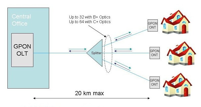
GPON SFP is a new higher-speed bi-directional optical transceiver, which can deliver 2.5 Gbits/sec of bandwidth. And it is a kind of single fiber transceiver which comes with SC connector and can transmit data up to 20km. In addition, it features a 28-dB optical loss budget to enable 1:64 split ratios and provides adequate optical loop lengths. Most EPON and some BPON systems deployed today use 25-dB optics, which limit the split ratio and loop length. For this reason, GPON transceiver enjoys the added advantage of industrial demand. The key performance advantage is to reduce the upstream split loss arising from utilizing the mode-coupled-receivers (MCR) in a PON application. Moreover, this innovative module dose not outweigh the costs over a standard module. For these two reasons, the GPON SFP modules are very attractive to the network operators to improve the utilization of GPON network. On top of that, GPON SFP transceiver is an essential part of GPON system which is necessary both for optical network unit (ONU) installed at the subscriber’s premises and for the optical line terminal (OLT) at the central office (CO). The following part will respectively introduce the GPON OLT, GPON ONU and GPON ONT SFP module.
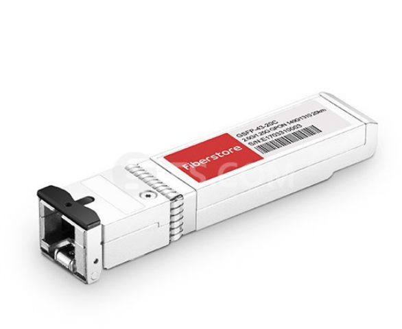
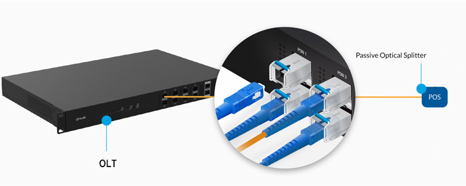
GPON OLT SFP is designed for OLT side in GPON network. OLT is a equipment integrating L2/L3 switch function, which is located in central office (CO). The main function is to control the information float in both directions: upstream and downstream. The GPON OLT module plays an inevitable role in the upstream and downstream transmission. In order to put across the transmission process, the downstream transmission is taken as an example. A single mode optical fiber coming from OLT (at the central office) PON port, runs to the passive optical splitter (POS) located near end users. And then the optical splitter will divide signals into separate paths which can provide service up to 64 end users. In this basic GPON topology, a GPON OLT module is used to connect a single-mode fiber patch cable to a passive optical splitter. Therefore, GPON OLT transceiver works to get the data, voice and video traffic from metro network or from a long-haul network.
Since the ONU and ONT are deployed at customer’s premises, they are connected to the OLT by means of optical fiber and no active elements are present in the link. In GPON network, the ONU/ONT transceiver is the physical connection between the customer premises and the central office OLT. This type of modules gets the signals from OLT, so they have the opposite characteristic of GPON OLT transceiver, incorporating a high performance 1310nm burst mode DFB transmitter and 1490nm CW mode APD receiver. By being plugged into advanced “triple play” (data, voice & video) ONT or ONU equipment (with SFP ports), such as Ethernet switches, routers, DSLAMs or home gateway, ONU/ONT SFP module fits seamlessly into existing communications equipment and provides end users with a smooth upgrade to GPON. Therefore, GPON ONU/ONT SFP module plays an important role in the applications for point-to-multipoint (P2MP) ONT / ONU equipment in GPON network.
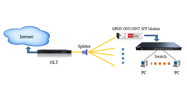
GPON SFP transceiver meets the the requirements of FTTx network to accelerate the speed or capacity. GPON OLT, ONU and ONT SFP module have their respective roles to play in the GPON networks. Many people may worry the high attenuation losses from optical splitter in the GPON networks, as above mentioned, the GPON optical module is just used to solve this problem in that it utilizes the MCR technology that protects large numbers of signals. In a word, this new module is a compelling network alternative to save cost and increase bandwidth and security.
Related Article: ABC of PON: Understanding OLT, ONU, ONT and ODNCopper SFP vs Optical SFP: Which One Is the Best to Use?
The war of copper vs fiber has raged for years. Fiber seems to operate as a rival to copper rather than a replacement until now, it has already established a niche in the industry. However, with recent advances in copper technology, the copper presents the same step-ladder upgrade path. The speed difference between the two media is considerably smaller. In some ways, the copper matters most to IT experts and data center decision makers. But many end-user organizations still face tough decision about which type is the best overall value for their current and future projected needs. This battle is also being waged in SFP transceivers, there is a measurable difference in the copper SFP vs optical SFP. This article will explore their respective strengths and weaknesses and reveal insights into how IT experts are to proceed.

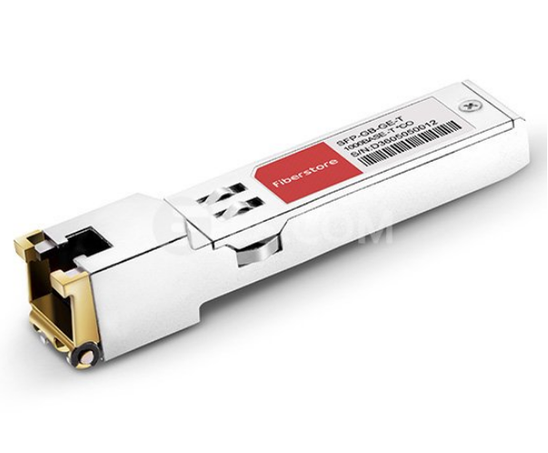
The Gigabit RJ45 copper SFP transceiver supports 1000Mbps over Cat5 cables with RJ45 connector interface, which operates on standard Cat5 unshielded twisted-pair copper cabling of link lengths up to 100 m (328 ft). GLC-T is a typical Cisco 1000BASE-T SFP copper RJ-45 transceiver. For short-distance links on a Gigabit switch, it makes no difference if you use SFP ports or RJ45 ports to interconnect switches. Copper SFP is popular to be used for short range uplinks, as it’s easier and cheaper to use 1G copper SFPs and patch cables. And SFP ports are primarily for allowing fiber connections over longer distances. Especially in some case, Copper SFP will make sense if the switch on one side does not have copper ports but SFP slots and the switch on the other side only has copper and can’t be fitted with fiber ports. Or if you don’t need the distance of fiber, you can consider converting SFP to RJ45, which will depend on the switch to determine what copper speeds (10/100/1000) are supported on a copper SFP. Moreover, using copper SFPs to connect the regular copper Gigabit ports is a wise choice to make the best use of the corresponding number of SFPs on existing connected switches.
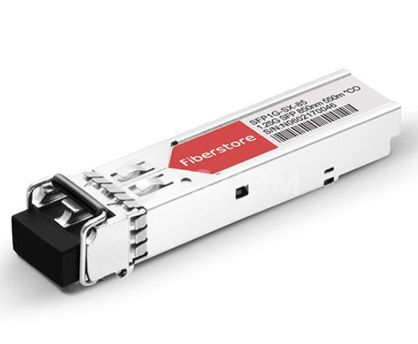
The optical fiber SFP modules with LC or SC optical connectors are available in Fast Ethernet and Gigabit Ethernet. And these SFP modules are industrially rated to perform in the most difficult operating environments. The SFP fiber module offers different wavelengths and optical power budget to allow distances from 550m to 120km. A variety of 1Gbps SFP modules in different distance can be found in FS.COM. Some statics also shows that the legacy SFP can hit 4.25Gb/s at 150m, or up to 1.25Gb/s for 160km runs and a variety of ranges/speeds in between depending on type of fibre. Generally, when the distance of the run is over 328 ft/100 m, fiber SFP module must be considered instead of copper SFP RJ45 module, since 1000Mbps could only go as far as 100m over copper cabling. In that sense, optical fiber SFP offers the substantial advantage over copper SFP.
- Operating Temperature
For the standard fiber SFP and copper SFP, there is no difference for the operating temperature - they support 0 to 70°C (32 to 158°F) case temperature as default. In fact, there is more heat dissipated for optical or electrical transmission in the specific applications. Generally, the copper SFPs run much hotter than the fiber SFPs. There are two factors that affect the temperature: power consumption and the case surface. The typical power consumption of fiber SFPs is 0.8W, the copper SFP is 1.05w, that's why copper SFP have a higher case temperature. In the same environment, the fiber SFP runs at 40°C (104°F) while the copper SFP should run around 52°C (126°F).
- Distance
As mentioned above, copper SFP supports the max cable distance is 100m, so it is commonly used to interconnect between switches and servers in horizontal and shorter-length backbone applications. While the fiber SFP allows the transmission distance up to 120km, which demonstrate the high performance over longer distances.
- Security
When security could be considered as a problem in the connection, using fiber SFP module is better than RJ45 copper SFP module. Because fiber doesn’t conduct electricity that makes it resistant to lightning strikes.
- Cost
Copper SFP transceiver might be more expensive than fiber SFP module in the same short distance. In Gigabit Ethernet applications, when copper SFP is used in combination with cooper cables in short runs, it is more cost effective as the copper cables are more cheaper than fiber cables. Besides, with the boom of third-party vendors, their full-compatible and trustworthy fiber SFP modules are developed to support lower cost fiber runs. The price gap between 100m copper transceiver and 40km 1000BASE-EX SFP fiber transceiver is reduced. More choices are provided for customers to meet their specific demands.
| FS P/N | Description | FS.COM Price |
| SFP-GB-GE-T | Cisco GLC-T Compatible 1000BASE-T SFP Copper RJ-45 100m Transceiver | $ 21.00 |
| SFP1G-SX-85 | Generic Compatible 1000BASE-SX SFP?850nm 550m DOM Transceiver | $ 6.00 |
| SFP1G-EX-55 | Cisco GLC-EX-SM1550-40 Compatible 1000BASE-EX SFP?1550nm 40km DOM Transceiver | $ 24.00 |
Through copper SFP vs optical SFP, we can see that each technology has its own set of advantages and disadvantages. Optical fibre SFP is not necessarily better than copper SFP. In fact, mixing copper and fiber solutions is the best practice for data center, as a versatile solution is critical to ensuring the data center remains both manageable and scalable when performance demands skyrocket. Network industry is unpredictable, and the demands of tomorrow may require facilities to investigate solutions they may have scoffed at a year ago.
A Brief Introduction of Cisco BiDi SFP Transceiver
In the early stage of optical fiber communication, one optical fiber can only transmit signals of one wavelength. This is known as conventional two-fiber Bi-Directional communication - at least two fibers are needed to accomplish the full-duplex communication with TX and RX optical signals. With the development of WDM technology, transmitting and receiving of optical signals on separate wavelength can be achieved through only one single fiber. This single fiber BiDi transmission gradually becomes a popular and cost-effective solution for today’s data center and IT infrastructure, because it helps to maximize the capacity and usage of optical fibers. Consequently, BiDi optical transceiver as the basic component plays an irreplaceable role in the WDM BiDi transmission application. This article will generally introduce Cisco BiDi SFP transceivers, including GLC-BX-U, GLC-BX-D, GLC-BX-20U, GLC-BX-20D, GLC-BX40-D-I, GLC-BX40-U-I, GLC-BX80-D-I, GLC-BX80-U-I, GLC-BX120-U, GLC-BX120-D, etc.
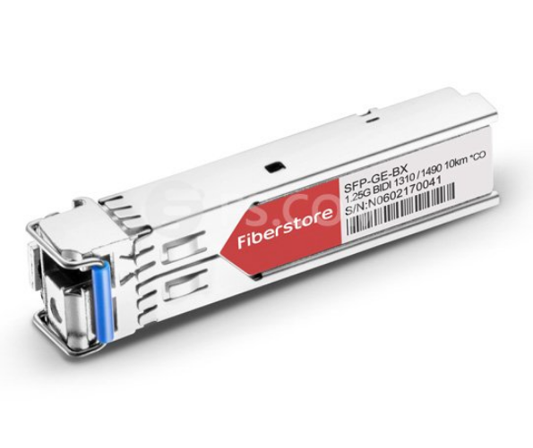
BiDi SFP transceiver can be defined as a compact, hot swappable, input/output optical module that can transmit and receive data to/from interconnected equipment through a single optical fiber. Unlike traditional optical transceivers, BiDi optical transceivers are fitted with wavelength division multiplexing (WDM) diplexers, which combine and separate data transmitted over a single fiber based on the wavelengths of the light. To simplify it, conventional optical module has two ports - the TX for the transmit port and the RX for receive port; but BiDi transceiver has only one port to complete the 1310nm optical signal transmitting and 1550nm optical signal receiving, or vice versa. Therefore, BiDi transceivers must be deployed in matched pairs with their diplexers tuned to match the expected wavelength of the transmitter and receiver. These BiDi optical transceivers can offer bi-directional data links over single-mode fiber up to 120 km. BiDi SFP transceiver is applicable to many access networks: passive optical networks (PON) and point-to-point, digital video and closed circuit television (CCTV) applications, inter-system communication between servers, switches, routers, optical add drop multiplexer (OADM), WDM fast Ethernet links, SDH/STM-1, SONET/OC3, metropolitan area networks and other optic link.

1G BiDi SFP is also known as 1000BASE-BX SFP, which use two different wavelengths (1310nm-TX/1490nm-RX, 1310nm-TX/1550nm-RX, 1490nm-TX/1550nm-RX and 1510nm-TX/1570nm-RX) for transmission in different distance. The following will list some main Cisco BiDi SFP modules in 10km, 20km, 40km, 80km and 120km.
The Cisco GLC-BX-D and GLC-BX-U is a pair of 10km BiDi SFP transceiver with LC duplex connectors, operating on a single strand of standard SMF. The GLC-BX-U transceiver operates at 1310nm-TX/1490nm-RX wavelength with upstream bidirectional single fiber, while the GLC-BX-D transceiver operates at 1490nm-TX/1310nm-RX wavelength with downstream bidirectional single fiber. These two BiDi optical modules, compliant to 1000Base-BX standard, are rated for distances up to 10 km over SMF and a maximum bandwidth of 1Gbps. A 1000BASE-BX-D device is always connected to a 1000BASE-BX-U device with a single strand of standard SMF. In addition, the GLC-BX-D and GLC-BX-U BiDi SFPs also support digital optical monitoring (DOM) functions according to the industry-standard SFF-8472 multisource agreement (MSA). This feature gives the end user the ability to monitor real-time parameters of the SFP, such as optical output power, optical input power, temperature and transceiver supply voltage.
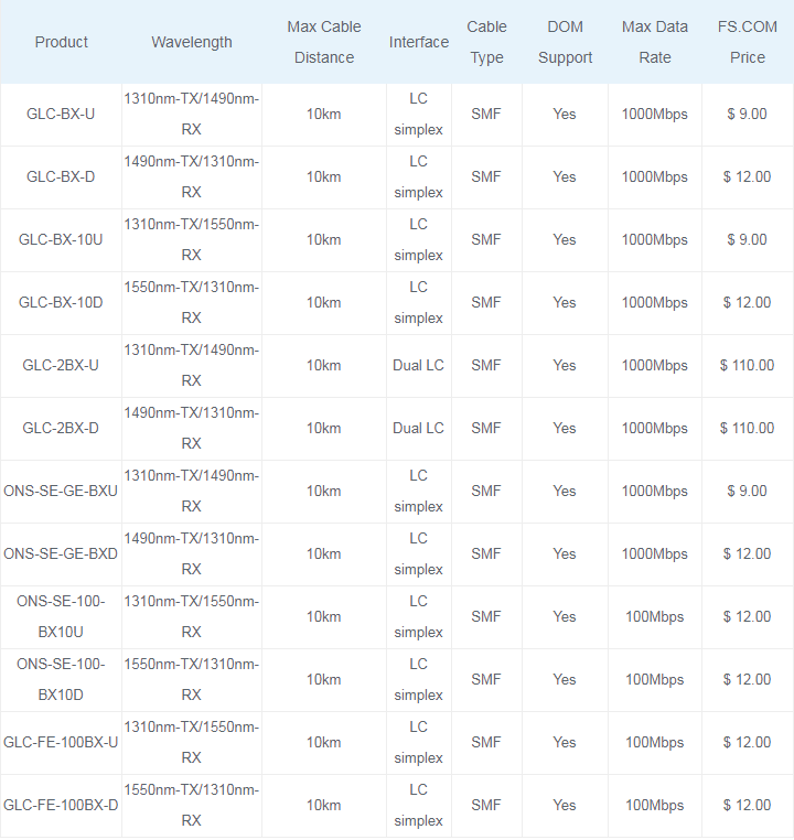
(GLC-2BX-U and GLC-2BX-D are 2-channel 1000BASE-BX SFP modules, also known as compact SFPs that integrate two IEEE 802.3ah 1000BASE-BX10 interfaces in one SFP module. They are designed to connect to any standard-based Customer Premises Equipment (CPE) in FTTx links.)
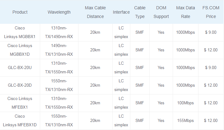
GLC-BX-20U and GLC-BX-20D are Cisco 20km BiDi SFP transceivers that work with single mode fiber. The GLC-BX-20U operates at 1310nm-TX/1550nm-RX wavelength, and GLC-BX-20D operates at 1550nm-TX/1310nm-RX. So these two BiDi SFPs always work in pairs. Their max data rate is 1000Mbps. FS.COM compatible Cisco BiDi transceivers are high performance, cost effective modules supporting data-rate of 1000Mbps and 20km transmission distance with SMF. Among the Cisco 20km BiDi SFPs, Cisco Linksys MFEBX1D provides up to 155Mbps bi-directional data transfer rate at distances up to 20km on a single fiber core. These bidirectional SFP transceivers allow data transfer in either direction through a single optical fiber by employing separate wavelengths travelling in either direction.
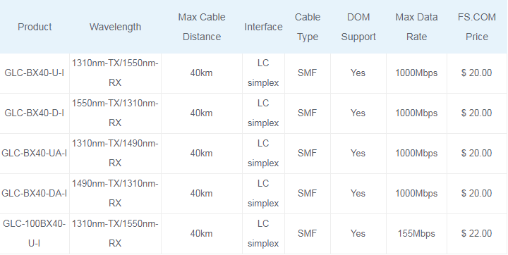
Cisco GLC-BX40-D-I and GLC-BX40-U-I is a pair of 40km BiDi SFP modules for Gigabit Ethernet 1000BASE-BX and Fiber Channel communications. They support link length of up to 40km point to point on single mode fiber at 1Gbps bidirectional and use an LC connector. The GLC-BX40-D-I is 1550nm-TX/1310nm-RX 40km BiDi WDM SFP simplex transceiver module, GLC-BX40-U-I is 1310nm-TX/1550nm-RX BiDi WDM SFP module. They are specified for duplex optical data communications such as 1000BASE-BX Gigabit Ethernet per IEEE802.3z and 1G Fiber Channel extended reach application.
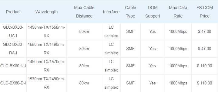
The Cisco GLC-BX80-D-I and GLC-BX80-U-I SFPs are 1G BiDi SFP modules that provide 80km transmission distance over single strand of single-mode fiber. GLC-BX80-D-I operates at 1570nm-TX/1490nm-RX wavelength, whereas GLC-BX80-U-I operates at 1490nm-TX/1570nm-RX. These bidirectional SFP transceivers are intended mainly for connecting high-speed hubs, Ethernet switches, and routers together in different wiring closets or buildings using long cabling runs, and developed to support longer-length on fiber backbones. Compared with commonly used dual fiber SFP transceiver modules, the BiDi SFP transceiver allows end users to reduce the total cost on fiber cabling infrastructure by requiring half of fiber cables, providing increased transmission capacity very convenient without installing new fibers.
The Cisco GLC-BX120-U and GLC-BX120-D are 1490nm and 1550nm bidirectional SFP transceivers that are used with single mode optical fiber. They also use two wavelength 1490nm-TX/1550nm-RX(1550nm-TX/1490nm-RX) simultaneously. These BiDi SFP modules can support transmission distance up to 120 km, which are connected through pluggable LC connector type optical interface. They have a DFB (Distributed Feedback) type transmitter, an APD (Avalanche Photo-Diode) type receiver, an LD (Laser Driver), a limiting amplifier and digital diagnostic monitor. Those BiDi SFP transceivers are Class 1 laser safety product which complies with US FDA regulations, SFP MSA, SFF-8472 and RoHS standards. More importantly, 120km SFP modules have the same or even lower transmit power as compared to 80km SFP. It is the reason that 120km modules extend the range thanks to receiver not transmitter. 120km modules have much better receiving sensitivity than 80km modules.

BiDi SFP transceiver serves as an ideal and feasible solution in situations where only limited fibers or limited conduit space is available. And the deployment of BiDi optical transceivers efficiently enhances the bandwidth capacity of the existing optical fiber infrastructure and help to achieve economical and reliable performance of the optical network. Although BiDi transceivers may be more expensive than common transceiver modules, they can save you the cost on fiber cables from the long run.
SFP-GE-S-2 VS. GLC-SX-MM: What’s the Difference?
SFP-GE-S-2 and GLC-SX-MM are Cisco 1000BASE-SX SFP multimode fiber transceivers. Since there are similar specifications for these two multimode modules, many end users may be confused when choosing a multimode fiber SFP LC connector SX transceiver for their Cisco switches. So, are they the same one? This post intends to give a simple explanation of SFP-GE-S-2 vs. GLC-SX-MM.
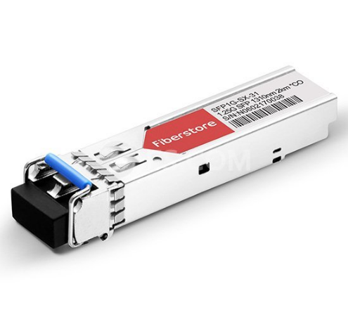
SFP-GE-S-2 Module
Cisco SFP-GE-S-2 is a 1 GbE SFP SX fiber transceiver that supports the maximum data rate of 1Gbps. It’s compatible with the IEEE 802.3z 1000BASE-SX standard, and can operate on standard multimode fiber optic link spans of up to 2 km.
| Module/Specs | Cisco SFP-GE-S-2 |
| Interface | LC duplex |
| Wavelength | 1310nm |
| Tx power | -9.5 ~ -3dBm |
| Receiver Sensitivity | < -17dBm |
| DOM Support | Yes |
| Temperature Range | 32℉to 158℉ (0℃?to 70℃) |
| Data Rat | 1G |
| Fiber Mode | MMF |
GLC-SX-MM Module
GLC-SX-MM transceiver is also a Cisco 1000BASE-SX fiber transceiver that designed for Gigabit Ethernet applications. This SX module is compatible with the IEEE 802.3z 1000BASE-SX standard, and can operate on standard multimode fiber optic link spans of up to 550m.
| Module/Specs | Cisco GLC-SX-MM |
| Interface | LC duplex |
| Wavelength | 850nm |
| Tx power | -9.5 ~ -3dBm |
| Receiver Sensitivity | < -17dBm |
| DOM Support | No |
| Temperature Range | 32℉to 158℉ (0℃?to 70℃) |
| Data Rat | 1G |
| Fiber Mode | MMF |
SFP-GE-S-2 VS. GLC-SX-MM
From the above specs comparison, we can learn that these two SX multimode modules support same data rate and operating temperature range. They all can operate on the multimode fiber optic cables. The main differences include:
- Wavelength
SFP-GE-S-2 can support a wavelength of 1310nm, whereas GLC-SX-MM works in 850nm.
- Transmission Distance
SFP-GE-S-2 can support up to 2km over laser-optimized 50 μm multimode fiber cable, while GLC-SX-MM can operate on legacy 50 μm multimode fiber links up to 550m.
- DOM Support
SFP-GE-S-2 can support DOM, but GLC-SX-MM does not have DOM function. DOM (Digital Optical Monitoring) is an important function available on fiber optic transceiver. It allows users to monitor parameters of modules, such as optical output power, optical input power, temperature, laser bias current and transceiver supply voltage. In real time, it offers users more convenience when using optical modules.
- Price
GLC-SX-MM is a legacy model, it doesn’t feature DOM function. It comes with the lowest price compared with other SX?modules . Take FS.COM compatible transceivers as example, SFP-GE-S-2 costs $ 11.00, while GLC-SX-MM is only $ 6.00.
Conclusion
From the contents above - SFP-GE-S-2 vs. GLC-SX-MM, we can draw a conclusion that?these two?SX multimode?fiber transceivers nearly can be used as the same one type module sometimes, but their existing differences still differ them from some applications. Most of the Cisco switches and routers support all two models, but please note, some of the switches require different models, you may visit Cisco SFP Compatibility Matrix for more detailed information.
SFP 40 km VS. DWDM SFP: Which to Choose?
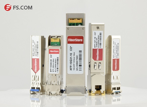
Small Form-factor Pluggable (SFP) is a compact, hot-pluggable transceiver used for both telecommunication and data communications applications. It is also called mini-GBIC for its smaller size, which is the upgraded version of GBIC transceiver. These 1Gb SFP modules are capable of supporting speeds up to 4.25 Gbps. And they are most often used for Fast Ethernet of Gigabit Ethernet applications. It interfaces a network device motherboard (for a switch, router, media converter or similar device) to a fiber optic or copper networking cable. SFP modules are commonly available in several different categories: 1000BASE-T SFP, 1000BASE-EX SFP, 1000BASE-SX SFP, 1000BASE-LX/LH SFP, 1000BASE-BX SFP, 1000BASE-ZX SFP, CWDM SFP and DWDM SFP. These modules support different distance according to the different Gigabit Ethernet standard. Today’s main subject will discuss SFP 40 km vs. DWDM SFP.
SFP 40 km
SFP 40 km transceiver is designed for highly reliable fiber optic network links up to 40 km. It is a cost effective transceiver designed to enable 1Gb for data center and core network applications. 1000BASE-EX SFP is the most popular SFP 40 km transceiver which runs on 1310nm wavelength lasers and achieves 40km link length. Except that, 1000BASE-BX BiDi SFP, 1000BASE-LH SFP and 1000BASE-LX SFP can also realize the transmission distance up to 40 km. The following will introduce these 1GbE SFP 40 km transceivers respectively.
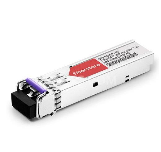
1000BASE-EX SFP transceiver module is designed to connect a Gigabit Ethernet port to a network and has dual LC/PC single mode connectors. It operates on standard single-mode fiber-optic link spans of up to 40 km in length. The SFP Ethernet module provides a dependable and cost-effective way to add, replace or upgrade the ports on switches, routers and other networking equipment. Cisco GLC-EX-SM1550-40 and Cisco GLC-EX-SMD are 1G single mode fiber SFP 40 km modules for 1000BASE-EX Gigabit Ethernet transmission. GLC-EX-SM1550-40 supports a 1550nm wavelength signaling, while GLC-EX-SMD supports a 1310nm wavelength signaling.
1000BASE-BX SFP is a kind of BiDi transceiver, which can be divided into 1000BASE-BX-D SFP and 1000BASE-BX-U SFP. These two SFP transceivers must be used in pairs to permit a bidirectional Gigabit Ethernet connection using a single strand of single mode fiber (SMF) cable. The 1000BASE-BX-D SFP operates at wavelengths of 1490nm TX/1310nm RX, and the 1000BASE-BX-U SFP operates at wavelengths of 1310nm TX/1490nm RX.
- 1000BASE-BX-D BiDi SFP 40 km
Cisco GLC-BX40-D-I and GLC-BX40-DA-I are pluggable fiber optical transceivers for Gigabit Ethernet 1000BASE-BX and Fiber Channel communications. They support link length of up to 40 km point to point on single mode fiber at 1Gbps bidirectional and use an LC connector. The GLC-BX40-D-I transceiver transmits a 1490nm channel and receives a 1310nm signal, whereas GLC-BX40-DA-I transmits at a 1550nm wavelength and receives a 1310nm signal.
- 1000BASE-BX-U BiDi SFP 40 km
Similar to 1000BASE-BX-D 40 km SFP , Cisco GLC-BX40-U-I and GLC-BX40-UA-I also support link length of up to 40 km point to point on single mode fiber at 1Gbps bidirectional and use an LC connector. The main difference is the wavelength: GLC-BX40-U-I transmits a 1310nm channel and receives a 1550nm signal, whereas GLC-BX40-UA-I transmits at a 1310nm wavelength and receives a 1490nm signal. A GLC-BX40-D-I or GLC-BX40-DA-I device connects to a GLC-BX40-U-I or GLC-BX40-UA-I device with a single strand of standard SMF with an operating transmission range up to 40 km.
1000BASE-LX is a standard specified in IEEE 802.3 Clause 38 which uses a long wavelength laser. The “LX” in 1000BASE-LX stands for long wavelength, indicating that this version of Gigabit Ethernet is intended for use with long-wavelength transmissions (1270 - 1355nm) over long cable runs of fiber optic cabling. Allied Telesis AT-SPLX40 and Allied Telesis AT-SPLX40/1550 are 1000BASE-LX SFP single-mode modules supports Gigabit Ethernet over single-mode cables at distances up to 40 km. AT-SPLX40 operates over a wavelength of 1310nm for 40 km, whereas AT-SPLX40/1550 operates over a wavelength of 1550nm.
Unlike 1000BASE-LX, 1000BASE-LH is just a term widely used by many vendors. Long Haul (LH) denotes longer distances, so 1000BASE-LH SFP modules operate at a distance up to 70 km over single mode fiber. Cisco Linksys MGBLH1 is a easy-to-install modules that provide a simple way to add fiber connectivity or to add an extra Gigabit Ethernet port to switches. The MGE transceiver can support distances up to 40 km over single-mode fiber at a 1310nm wavelength.
DWDM SFP
DWDM SFP transceivers are used as part of a DWDM optical network to provide high-capacity bandwidth across an optical fiber network, which is a high performance, cost effective module for serial optical data communication applications up to 4.25Gb/s. DWDM transceiver uses different wavelengths to multiplex several optical signal onto a single fiber, without requiring any power to operate. There are 32 fixed-wavelength DWDM SFPs that support the International Telecommunications Union (ITU) 100-GHz wavelength grid. The DWDM SFP can be also used in DWDM SONET/SDH (with or without FEC), but for longer transmission distance like 200 km links and Ethernet/Fibre Channel protocol traffic for 80 km links. Cisco C61 DWDM-SFP-2877-40 is a 1000BASE-DWDM SFP 40km transceiver, which is designed to support distance up to 40 km over single-mode fiber and operate at a 1528.77nm DWDM wavelength (Channel 61) as specified by the ITU-T.
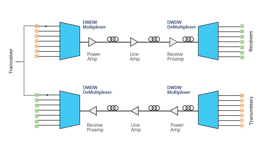
SFP 40 km VS. DWDM SFP
- Transmission Medium
Generally, the standard SFP 40 km transceivers transmit through the single mode fiber, while DWDM SFP carries signals onto a single optical fiber to achieve maximum distances by using different wavelengths of laser light. So the DWDM SFP transceivers do not require any power to operate.
- Wavelength
The standard SFP 40 km transceivers support distances up to 40 km over single-mode fiber at a 1310nm/1550nm wavelength. (the BiDi SFP has 1490nm/1550nm TX & 1310nm RX or 1310nm TX & 1490nm/1550nm RX ). However, DWDM SFP operates at a nominal DWDM wavelength from 1528.38 to 1563.86nm onto a single-mode fiber. Among them, 40 km DWDM SFP operates at a 1528.77nm DWDM wavelength (Channel 61).
- Application
DWDM SFP is used in DWDM SONET/SDH, Gigabit Ethernet and Fibre Channel applications. These modules support operation at 100Ghz channel. The actual SFP transceiver offers a transparent optical data transmission of different protocols via single mode fiber. And for back-to-back connectivity, a 5-dB inline optical attenuator should be inserted between the fiber optic cable and the receiving port on the SFP at each end of the link.
- Price
DWDM provides ultimate scalability and reach for fiber networks. Boosted by Erbium Doped-Fiber Amplifiers (EDFAs) - a sort of performance enhancer for high-speed communications, DWDM systems can work over thousands of kilometers. Most commonly, DWDM SFP is much more expensive than the standard SFP. You can see the price more clearly in the following cable.
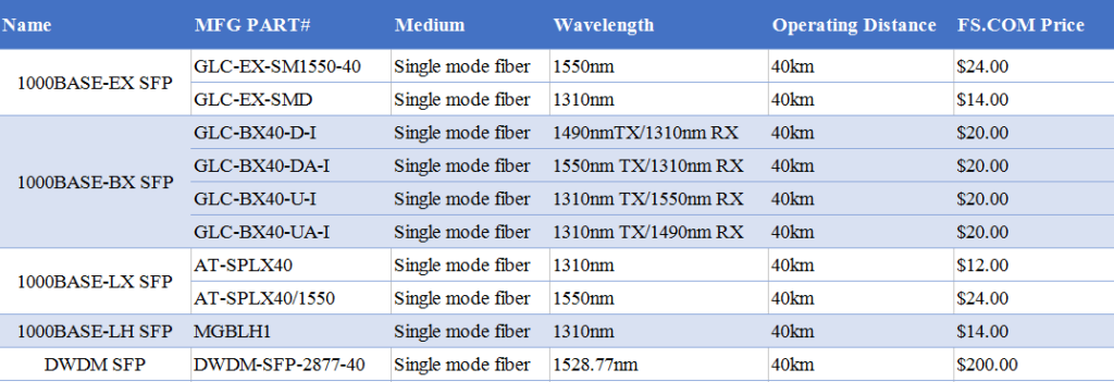
Conclusion
1000BASE SFP transceiver is the most commonly used component for Gigabit Ethernet application. With so many types available in the market, careful notice should be given to the range of differences, both in distance and price of multimode and single-mode fiber optics. Through SFP 40 km vs. DWDM SFP, if you are looking for SFP modules over long distance and with better scalability, DWDM SFP module is the ideal choice.
Related Article: SFP Transceiver: To Be or Not To Be?
EPON SFP VS. GPON SFP: Cost-effective Solution for Access Network
With the increasing demands for higher capacity, more diversity and more personalization of services, the capacity and versatility of access networks needs to be expanded. Passive optical network (PON), as a major technology of FTTH, offers point-to-multipoint (P2MP) network access with lower installation and maintenance costs. EPON (Ethernet PON) and GPON (Gigabit PON) are popular versions of PONs at present. The related technologies keep developing and meanwhile the market of PON components keep growing. PON transceiver (EPON SFP or GPON SFP) is an essential part of PON system, in which a single fiber from a central office optical network unit (ONU) is connected to optical network terminals (ONTs) or optical network units (ONUs) at costomer premises. EPON SFP vs. GPON SFP is today’s main subject matter of this paper.

Passive Optical Network (PON)
Passive optical network (PON) is a form of fiber-optic access network. As the leading technology being used in FTTx (FTTH) deployments, so it is also called FTTH (fiber to the home) network. The typical PON arrangement is a point to multi-point (P2MP) network where a central optical line terminal (OLT) at the service provider’s facility distributes TV or Internet service to as many as 16 to 128 customers per fiber line. A PON reduces the amount of fiber and central office equipment required compared with point-to-point architectures. PON only uses fiber and passive components, thus it costs significantly less than those using active components. However, a PON has a shorter range of coverage limited by signal strength, which is typically limited to fiber cable runs of up to 20 km (12 miles). There are two different solutions developed by the IEEE and ITU-T - EPON and GPON. The main differences between them lie in the protocols used for upstream and downstream communications. The following table shows the detailed information about EPON vs. GPON.

Table 1: EPON vs. GPON
What Is PON Transceiver?
PON transceiver is a bi-directional optical transceiver that uses different wavelengths to transmit and receive signals between the OLT at the CO and the ONUs at the end users’ premises over a single fiber. According to the pluged-in device, PON transceiver can be divided into OLT transceiver module and ONU transceiver module with SFF, SFP/SFP+ or XFP package. Here mainly introduce two common OLT transceivers used in GPON or EPON network: GPON SFP and EPON SFP.

GPON SFP OLT transceiver is designed for OLT side in GPON network. GPON SFP uses 1490nm continuous-mode transmitter and 1310nm burst-mode receiver. The transmitter section uses a 1490nm DFB (Distributed Feed Back) LD with automatic power control (APC) function and temperature compensation circuitry to ensure stable extinction ratio overall operating temperature range. And it is Class I laser compliant IEC825 and CDRH standards. The receiver has a hermetically packaged burst-mode APD-TIA (trans-impedance amplifier) pre-amplifier and a burst-mode limiting amplifier with LVPECL compatible differential outputs. The GPON OLT SFP transceiver is a high performance and cost-effective module for serial optical data communication applications to 2.5Gpbs. For GPON transceivers, there are 2 Class available - Class B+ and Class C+. The table below shows the key differences between GPON SFP class B+ and class C+:

Table 2: GPON SFP class B+ vs. GPON SFP class C+
EPON SFP transceiver is the family of high performance optical modules providing a symmetric 1.25 Gb/s downstream and 1.25 Gb/s upstream data link over a single fiber using a 1490 nm continuous-mode transmitter and 1310 nm burst-mode receiver. The transmitter section uses a 1490nm DFB laser for superior performance and is Class 1 laser compliant. The receiver section uses a 1310nm APD, pre-amplifier, and limiting post-amplifier. The receiver does not require a reset pulse between incoming optical packets of varying signal strength. EPON SFP OLT transceivers support 1000BASE-PX20-D for 20 km applications.
EPON SFP VS. GPON SFP
In terms of OLT module, there are many similarities through EPON SFP?vs. GPON SFP, such as type of laser, transmission distance and communication model. The key difference among them is the sending power and receiver sensitivity. The sending power of GPON SFP Class B+ is 1.5~5dBm, and its receiver sensitivity is -28dBm while the sending power of Class C+ is 3~7dBm and receiver sensitivity is -32dBm. The sending power of EPON SFP is 2~7dBm and its receiver sensitivity is -28dBm. For GPON SFP, the upstream bandwidth is scalable from 155Mbps to 2.5Gbps while the downstream is designed to deliver 1.25Gbps or 2.5Gbps. It is the most widely used consumer broadband service in FTTH networks of present times. On the other hand, EPON SFP supports symmetric bandwidth of 1.25Gbps in both the upstream and downstream directions.

Table 3: EPON SFP vs. GPON SFP
Conclusion
Through EPON SFP VS. GPON SFP, we can see that they are the same in architecture but for different data rate and applications. In terms of cost, The GPON SFP optical module is more expensive than EPON SFP. Because the GPON chipsets available in the market are mostly based on FPGA (Field Programmable Gate Array), which is more expensive than the EPON MAC (Media Access Control) layer ASIC. When GPON reaches deployment stage, the estimated cost of a GPON OLT is 1.5 to 2 times higher than an EPON OLT. For the users who have demands of multi-service, high QoS and security, as well as ATM backbone network, GPON SFP seems to be an ideal. And for the one who is much care about the cost and has less security requirements, EPON SFP may be better.
Where to Buy Reliable Low Cost 1000BASE-T SFP Modules?
Gigabit Ethernet, as a part of the Ethernet family of computer networking and communication standards, has been in the market for more than 15 years. 1000BASE-T Gigabit Ethernet is the most successful networking technology in the history. Delivering Gigabit performance over up to 100 meters of twisted pair cabling (Cat5 UTP), it is ideal solution to upgrade network smoothly without change its original architecture and decrease the cost of upgrading for a wide range of enterprise and embedded networking applications. When investing in 1000BASE-T SFP modules to keep the highest working quality for business, everyone wants to find the best deals when they come to their network hardware, but also with the same compliance certification and quality. So where to buy reliable low cost 1000BASE-T SFP modules? This article will tell you answer.
1000BASE-T SFP copper transceiver is based on the SFP Multi Source Agreement. It is compatible with the Gigabit Ethernet and 1000BASE-T standards as specified in IEEE 802.3z and 802.3ab. This Gigabit RJ45 copper SFP transceiver module supports 1000Mbps over Cat5 cables with RJ45 connector interface, which operates on standard Cat5 unshielded twisted-pair copper cabling of link lengths up to 100 m (328 ft). So those 1G copper SFPs can plug into any standard SFP interface allowing for 1000BASE-T Gigabit transmission. When referring to the types of 1000BASE-T copper SFP modules, there are generally three types provided by Cisco: Cisco GLC-T, Cisco GLC-TE, Cisco SFP-GE-T.
GLC-T is the Cisco 1G copper SFP, which is compliant to IEEE 802.3, and operates over Cat5 copper wire for a distance of 100m. It provides 1Gbps data transfer and full-duplex Gigabit Ethernet connectivity to high-end workstations and between wiring closets over existing copper network infrastructure.
Similar to GLC-T SFP modules, GLC-TE provides a link length of 100m over Cat5 copper wires. The only difference between these two SFP modules lies in the operating temperature range. GLC-T SFP is commercial temperature range (COM) from 0 to 70°C (32 to 158°F), while GLC-TE is Extended temperature range (EXT) from -5 to 85°C (23 to 185°F).
SFP-GE-T is Cisco copper SFP transceiver that works with 1000BASE-T. This 1Gb SFP RJ45 module is with spring latch for high density applications. The most difference is that SFP-GE-T has the function of NEBS 3 ESD. (NEBS is short for Network Equipment Building System and is a set of standards for building networking equipment which can withstand a variety of environmental stresses.) Therefore, SFP-GE-T supports extended working temperature.
There are all sorts of resources to get the most out of technology budget, especially when it comes to find the Cisco 1000BASE-T SFP modules either for brand new, refurbished, or gently used. What are the best ways to find them for a much more inexpensive price?
- Online Retailers
Online retailers with warehouses not only provide consumer-side purchasing with modules and networking hardware, they can also be a valuable asset to all sorts of companies looking to spend less money on equipment. There are online retailers that give almost as high as 90% discounts and price reductions. You need to be careful when it comes to certain warehouses as they might have huge savings but the parts might be used or not of the highest quality.
- Certified Sellers
Certified sellers, or re-sellers, can offer brand new or refurbished modules with great prices. Besides, they have professionals who can help you with all of your technology questions and make sure that you get the best deal.
- Third-Party Companies
In fact, there are many third party vendors to manufacture compatible SFP modules, such as FS.COM, 10GTek, Finisar, Fluxlight etc. Many people are confused about whether I should use 3rd party SFP modules. Most "third party” transceivers are made and assembled in exactly the same plants assembling officially-branded transceivers. There is almost no big difference between an official Cisco transceiver and a third-party plug, aside from the branding and about two hundred to a few thousand bucks. And now, using 3rd party SFP modules seems to more and more popular, as many 3rd party SFP module vendors are providing high quality and reliable 3rd party SFP modules with low prices. Besides, third-party SFPs can be as reliable as official OEM products.
| Copper SFP Models | Description | Operating Temperature Range | FS.COM Price | Fluxlight Price |
| Cisco GLC-T | 1000BASE-T SFP Copper RJ-45 100m Transceiver | COM | $ 21.00 | $ 44.00 |
| Cisco GLC-TE | 1000BASE-T SFP Copper RJ-45 100m Transceiver | EXT | $ 21.00 | $49.00 |
| Cisco SFP-GE-T | 1000BASE-T SFP Copper RJ-45 100m Transceiver | NEBS 3 ESD EXT | $ 21.00 | $44.00 |
The 1000BASE-T SFP copper transceiver offers a flexible and simple method to be installed into SFP MSA compliant ports at any time with no interruption of the host equipment operation. It enables for seamless integration of fiber with copper LAN connections wherever SFP interface slots can be found. Such system is economical, it saves time, offers flexibility and eliminates the necessity for replacing entire devices once the customers have to change or upgrade fiber connections and you will benefit so much from it.
Related Article: GLC-T vs GLC-TE vs SFP-GE-T: Which One to Choose?10G DWDM Tunable XFP - Up to 80 km Reach
With the spread of cloud computing and mobile broadband service, the volume of communications traffic has rapidly increased. In order to enable high-capacity optical networks, using a single optical fiber for optical signals of several different wavelengths in DWDM system is widely used. For this reason, tunable transceiver that enables ROADM functionality in next-generation networks is becoming more and more popular. In today’s market, there are mainly two kinds of tunable DWDM transceivers: tunable XFP and tunable SFP+. This article will take you to explore the DWDM C-band tunable XFP transceiver with 40 / 80 km transmission distance options.
Tunable XFP transceiver is an integrated fiber optic transceiver that provides a high-speed serial link at signaling rates from 9.95 Gbps to 11.35 Gbps. It complies with the ITU-T G.698.1 S-D100S1-2D standard with 50GHz channel spacing for SONET/SDH, IEEE DWDM 10GBASE-ZR for 40 or 80 km reach (Ethernet), and DWDM 10G FC (Fibre Channel) for 40 or 80 km reach applications. Tunable XFP can be tuned from channel C17 (1563.86nm) to C61 (1528.38nm). The maximum distance of this transceiver on a single mode fiber is up to 80 km. As mentioned above, tunable XFP optical transceiver is a full-duplex serial electric, serial optical device with both transmit and receive functions contained in a single module. On the transmit side, the 10 Gbps serial data stream is recovered, retimed, and passed to a modulator driver. The modulator driver biases and modulates a C-band-tunable integrated laser Mach-Zehnder (ILMZ), enabling data transmission over singlemode fiber through an industry-standard LC connector. On the receive side, the 10 Gbps optical data stream is recovered from an APD/transimpedance amplifier, retimed, and passed to an output driver. This module features a hot-pluggable XFI-compliant electrical interface. Here is a simple picture showing its working process.
- 50 GHz ITU channel spacing with intergrated wavelength locker
- Available in all C-Band Wavelengths on the DWDM ITU grid
- Available distances 40 or 80 km
- Supports 9.95Gb/s to 11.35Gb/s
- Built-in Digital Diagnostic Functions
- Tempereature Range: -5°C to 70°C
There are two transmission distance options for tunable XFP transceiver: 40 km or 80 km. Tunable XFP DWDM 80 km transceiver is designed for long distance optical communications up to 80 km with signaling rates up to 10Gbps. Obviously, the main difference is transmission distance. On account that 10G tunable DWDM XFP optical transceiver provides digital diagnostic functions via a 2-wire serial interface, which allows real-time access to the following operating parameters: transmitted optical power, received optical power, transceiver temperature, laser bias current and transceiver supply voltage. Therefore, the differences between 40 km tunable XFP and 80 km tunable XFP mainly lie on theses parameters. One thing to note is that 40 km tunable XFP optics is designed with high performance PIN receiver, while the 80 km tunable XFP transceiver is APD receiver. The APD (avalanche photodiode) receiver employed in these extended-reach optical transceivers has an enhanced sensitivity to allow for these extended distance fiber runs. However, it is to be noted that the input power is typically between -7 and -24 dBm. Therefore, the receiver sensitivity between these two distance has a big difference. Generally, the max receive dBm of 40 km tunable XFP transceiver is -15, while the 80 km tunable XFP transceiver is -24. And for power budget, 40 km tunable XFP is 14dB while a distance up to 80 km is up to 22dB power budget. The following table lists the main differences.
In general, the channel switching of tunable switches can enable the service operators to turn up circuits faster and reduce their sparing costs dramatically in today’s DWDM systems. On the other hand, tunable transceiver is usually two or four times more expensive than the regular static DWDM optical module, because a special tunable laser is applied in it. Tunable XFP transceiver provides a full C-band window covering 1528nm to 1566nm for DWDM optical networks, which meets the need of rapid increase in the volume of communications traffic from telecom carrier and operator. The tunable DWDM XFP module can replace the fixed DWDM channel XFP transceivers that are currently used, while reduce the large stock since all wavelengths can now be covered with one transceiver module.
| Model | Frequency | Wavelength | Fiber Type | Connector | Price on FS.COM |
| ONS-XC-10G-C | 50 GHz | 1563.86~1528.3 | SMF | LC | $1,400 |
| XFP-10G-CBAND-T50-ZR | 50 GHz | 1563.86~1528.3 | SMF | LC | $1,400 |
| NTK583AAE6 | 50 GHz | 1563.86~1528.3 | SMF | LC | $1,400 |
| TDXFP-10GHXXX-80 | 50 GHz | 1563.86~1528.3 | SMF | LC | $1,400 |
| TDXFP-10GHXXX-40 | 50 GHz | 1563.86~1528.3 | SMF | LC | $1,400 |
Unveil 10G DWDM Tunable SFP+
Optical transceivers play a key role in handling all storage, data, voice and video traffic whether linking rack to rack, bottom to top of rack, data center to data center or enterprise networks to network. A range of flexible fiber optic transceiver modules cover all of network needs, such as SFP, SFP+, QSFP, QSFP28, CFP, etc. But for 10G DWDM tunable SFP+, many people might find themselves in the mire. When I first heard about this tunable transceiver, I thought that it would definitely bring revolutionary change to future metro Ethernet and optical transport networks with its important practical value for flexibly selecting working wavelength. So this article will unveil all of the things about tunable SFP+ optical transceiver.

As the demand for great traffic capacity keeps growing, more optical transceivers of different wavelengths are needed. So tunable transceivers are recent innovations in DWDM transport systems. DWDM tunable transceivers are within the scope of DWDM transceivers, through which different DWDM wavelengths can be configured and output in the same optical module. But compare with conventional fixed-wavelength DWDM SFP+, the tunable SFP+ uses tunable laser as light sources in DWDM systems, which is tunable across the entire C-band with 96 channels on the ITU-T 50-GHz grid.
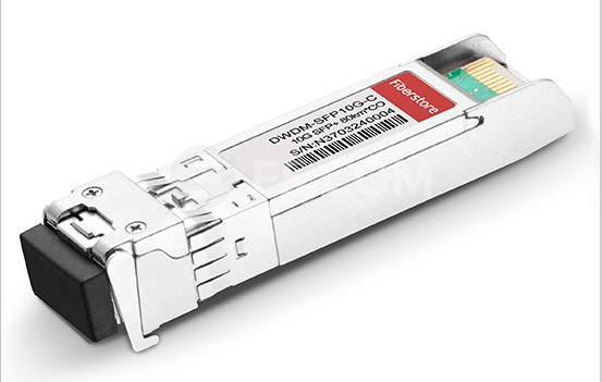
The tunable laser technology is firstly introduced by Oclaro, a leading supplier and and innovator of tunable laser and transceiver solutions. In 2013, it announced a standards-compliant, multi-rate tunable SFP+, which supports rates between 9.95 and 11.3 Gbps. But the first-generation tunable SFP+ optical transceivers were not widely adopted, because they did not meet the critical requirement of less than 1.5 W of power consumption at high operating temperatures. So in 2014, Oclaro demonstrated a new tunable SFP+ module based on a new Oclaro InP tunable laser platform. With the innovative new chip design and the use of next generation materials, the new module is fully compliant to the SFP MSA form factor and can operate at 1.5W at 70 degrees C with excellent OSNR tolerance. With the breakthrough of technology, the 10G tunable SFP+ transceivers become an important component for next generation data center, metro and regional optical network equipment. They meet the world’s growing bandwidth demands while reducing the size and power consumption for 10G connections.
(1) Fully compliant with MSA standard size based on SFF-8432 specification for Improved Pluggable Form Factor, rev. 5.1
(2) Tunable across the full C-band with 96 channels on the ITU-T 50GHz grid
(3) Multi-rate operation: 9.95 Gbit/s to 11.3 Gbit/s
(4) Operates at 1.5W at 70 degrees C with excellent OSNR tolerance
The tunable SFP+ transceivers are high-performance optics which can be tuned to the appropriate wavelength. The ability to operate on various wavelengths has set these optics apart from fixed-wavelength DWDM SFP+. Besides, These tunable optics will become popular among DWDM systems due to the several advantages.
- Flexible network management
A tunable SFP+ transceiver will be remotely configured for a specific wavelength to support bandwidth changes as needed in Enterprise or Metro networks.
- Reduced network inventory
One tunable SFP+ transceiver will support more than 80 different wavelengths. It will allow network operators to hold one tunable device code as opposed to 80+ fixed wavelength transceivers.
- Reduced power consumption
It will provide a significant reduction in electrical power dissipation compared to other tunable solutions.
- Compact and high-density form factor
The new tunable SFP+ transceiver will be about the size of a pack of gum, saving valuable real estate in data centers.
- Increased network capacity
The tunable SFP+ will double the number of channels supported in this compact transceiver form factor. Upgrading to 50GHz channel spacing doubles the capacity potential in Enterprise and Metro networks.
The advent of 10G DWDM tunable SFP+ transceivers in the market will accelerate the trend for pace-, power-, and cost-efficient network solutions. Because tunability is critical for minimizing inventory and enabling flexible rapid service provisioning. Although now the market share for DWDM tunable SFP+ transceiver is not big enough, the huge potential will be demonstrated in the near future.
Original Source: www.fiber-optic-components.com/unveil-10g-dwdm-tunable-sfp.html
Optics Solutions for Netgear ProSAFE XS712T (XS712T-100NES)
With the growth of virtualization, cloud-based services and applications like VoIP, video streaming and IP surveillance, SMB networks need to extend beyond simple reliability to higher speed and performance. As a leading provider of networking equipment for SMBs, Netgear had launched a variety of cost-effective 10GBASE-T switches including Netgear ProSAFE XS708Ev2, XS716E, XS708T, XS712T, XS716T, XS728T, XS748T and XSM7224. When looking for a lower cost and high capacity 10GBASE-T switch in SMB home/office lab environments, the Netgear ProSAFE XS712T is one of the best options. It comes in at around $1,100 at Amazon which is more budget friendly than the larger data center switches. This article will review the Netgear ProSAFE XS712T (XS712T-100NES) 10GBASE-T switch.
Netgear ProSAFE XS712T is a powerful smart managed switch that comes with 10 dedicated 10GBASE-T RJ-45 copper ports supporting 100M/1G/10G speeds and 2 combo copper/SFP+ fiber 10G ports. The 2 combo SFP+ ports can be used as 10GASE-T ports or as SFP+ 10Gb Ethernet ports. This is an awesome feature as it allows an inexpensive SPF+ link via DAC to a 24 or 48 port 1Gb Ethernet switch for non-10Gb networking needs. All ports can automatically negotiate to the highest speed, which makes the switch ideal for environments that have a mix of Ethernet, Fast Ethernet, Gigabit Ethernet, or 10-Gigabit Ethernet devices. Cat 5e/Cat 6/Cat 6a/Cat 7 can be used to make 10G connections. Cat 6a/Cat 7 cables are recommended if the cable distance is greater than 45 meters. Besides, the smart switch can be freestanding or rack mounted in a wiring closet or equipment room. This 10G smart managed switch is purposely designed as a cost-effective way to provide 10G connections to 10G-capable servers and NAS (Network Attached Storage) systems. It also can be used at the center of a small business network or as an aggregation/access switch in a larger organization.

Figure 1: Netgear ProSAFE XS712T (Source: www.netgear.com )
In order to meet the current and future needs on virtualization, converged network and mobility, the XS712T provides comprehensive L2+/Layer 3 Lite features, such as VLAN, QoS, IGMP and MLD snooping, Static Routing, Link Aggregation, ACL binding. Besides, it has an easy-to-use Web-based management GUI which makes setup and management simple. Some of main features include:
The RJ-45 copper ports of XS712T comply with IEEE 10GBASE-T standards. They support low-latency, line-rate 10G copper “Base-T” technology with backward compatibility to Fast Ethernet and Gigabit Ethernet. So it allows for a cost effective and simpler upgrade path to 10-Gigabit Ethernet. The existing Cat5/Cat5e is supported for Gigabit speeds up to 100 meters, Cat6 for 10-Gigabit speeds up to 45 meters and Cat6a/Cat7 for 10GBASE-T connection up to 100 meter.
The powerful L2+/Layer 3 Lite features make XS712T the most cost-effective core switches for SMB and virtualization environment. This switch is also a future-proofing choice with 10G bandwidth, advanced traffic management and comprehensive IPv6 support.
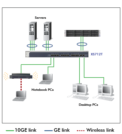
Figure 2: Netgear ProSAFE XS712T in SMB Network (Source: www.netgear.com )
The XS712T used as a aggregation switch has many useful purposes. It can help to resolve the congestion issue between network edge and core, which is caused by the broader adoption of Gigabit-to-the-desktop. Unlike multiple Gigabit Ethernet links, it provides greater scalability resulting in a simplified and highly efficient network infrastructure. What’s more, it can reduce cabling complexity because it can use existing cabling efficiently.
As mentioned above, The Netgear ProSAFE XS712T smart switch provides 12 twisted-pair ports that support nonstop 100M/1000M/10G networks. The switch also has two built-in SFP+ GBIC combo slots that support 1000M and 10G optical modules. Using these Gigabit slots, 100M/1000M/10G copper and 1000M/10G fiber connectivity can create high-speed connections to a server or network backbone. So 1000BASE-T SFP copper transceiver, 1000BASE SFP and 10G SFP+ transceivers are suitable for this switch. The following table lists the compatible transceivers and optic cables from FS.COM.
| MFG PART# | Description |
| AGM734 | NETGEAR AGM734 Compatible 1000BASE-T SFP Copper 100m Transceiver, RJ-45 Interface |
| AGM731F | NETGEAR Compatible 1000BASE-SX SFP 850nm 550m DOM Transceiver, LC Interface |
| AGM732F | NETGEAR Compatible 1000BASE-LX SFP 1310nm 10km DOM Transceiver, LC Interface |
| AXM761 | NETGEAR Compatible 10GBASE-SR SFP+ 850nm 300m DOM Transceiver, LC Interface |
| AXM762 | NETGEAR Compatible 10GBASE-LR SFP+ 1310nm 10km DOM Transceiver, LC Interface |
| AXM763 | NETGEAR Compatible 10GBASE-LRM SFP+ 1310nm 220m DOM Transceiver, LC Interface |
| AXM764 | NETGEAR Compatible 10GBASE-LR Lite SFP+ 1310nm 2km DOM Transceiver, LC Interface |
| AXC761 | 1m NETGEAR Compatible 10G SFP+ Passive DAC |
| AXC763 | 3m NETGEAR Compatible 10G SFP+ Passive DAC |
The Netgear XS712T (XS712T-100NES) provides a solid cost-effective solution especially for those with SMB home/ office lab environments. If you are seeking for afforable 10GBASE-T switch for your home lab, the XS712T can be taken into consideration. What’s more, the compatible fiber transceivers and cables can be found in many third party vendors with reasonable prices, such as cablestogo, fluxlight, smartoptics, FS.COM, and etc. You have a lot of choices to save money.
